
Loop simulation apparatus, method and program thereof

a technology of loop simulation and loop, which is applied in the field of loop simulation apparatus, method and program thereof, can solve the problems of difficult to simulate the curl at the ends of knitted fabric, the difficulty of simulating the three-dimensional structure of knitted fabric, and the bulging knitted fabric such as the pin tuck pattern, so as to facilitate the determination of tension, distortion angle, and bending angl

Active Publication Date: 2010-06-10
SHIMA SEIKI MFG LTD
View PDF4 Cites 13 Cited by
  • Summary
  • Abstract
  • Description
  • Claims
  • Application Information

AI Technical Summary

Benefits of technology

[0006]The basic objects of the present invention are to minimize the use of empirical rules during a loop simulation while keeping the calculation load within a feasible range, and to express three-dimensional bulges, curls and so on of a knitted fabric.
[0007]A loop simulation apparatus according to the present invention is an apparatus for creating a knitted fabric image corresponding to design data of a knitted fabric such that a loop of each individual stitch is represented, characterized by: means for determining a distance deviation between a distance from each individual stitch on the knitted fabric image to an adjacent stitch and a standard value thereof as a tension; means for determining a deviation between an intersection angle between a line linking each individual stitch on the knitted fabric image to an adjacent stitch in a course direction and a line linking each individual stitch on the knitted fabric image to an adjacent stitch in a wale direction and a standard value thereof as a distortion angle; means for determining a deviation between an angle between two stitches adjacent to each individual stitch on the knitted fabric image in the wale direction, with respect to an axis expressing an orientation of each individual stitch on the knitted fabric image to an adjacent stitch in the course direction, and a standard value thereof as a bending angle about a course axis; means for determining a deviation between an angle between two stitches adjacent to each individual stitch on the knitted fabric image in the course direction, with respect to an axis expressing an orientation of each individual stitch on the knitted fabric image to an adjacent stitch in the wale direction, and a standard value thereof as a bending angle about a wale axis; and shifting means for shifting a position of each individual stitch on the knitted fabric image to reduce the tension, the distortion angle, the bending angle about the course axis, and the bending angle about the wale axis.
[0008]A loop simulation method according to the present invention is a method for creating a knitted fabric image corresponding to design data of a knitted fabric such that a loop of each individual stitch is represented, characterized by the steps of: determining a distance deviation between a distance from each individual stitch on the knitted fabric image to an adjacent stitch and a standard value thereof as a tension; determining a deviation between an intersection angle between a line linking each individual stitch on the knitted fabric image to an adjacent stitch in a course direction and a line linking each individual stitch on the knitted fabric image to an adjacent stitch in a wale direction and a standard value thereof as a distortion angle; determining a deviation between an angle between two stitches adjacent to each individual stitch on the knitted fabric image in the wale direction, with respect to an axis expressing an orientation of each individual stitch on the knitted fabric image to an adjacent stitch in the course direction, and a standard value thereof as a bending angle about a course axis; determining a deviation between an angle between two stitches adjacent to each individual stitch on the knitted fabric image in the course direction, with respect to an axis expressing an orientation of each individual stitch on the knitted fabric image to an adjacent stitch in the wale direction, and a standard value thereof as a bending angle about a wale axis; and shifting a position of each individual stitch on the knitted fabric image to reduce the tension, the distortion angle, the bending angle about the course axis, and the bending angle about the wale axis.

Problems solved by technology

However, this method is problematic in that:the basis for the loop simulation is dependent on an empirical rule, and therefore ambiguous, andit is difficult to simulate a bulging knitted fabric such as a pin tuck pattern.
Furthermore, it is difficult to simulate the curl at the ends of the knitted fabric.The latter two problems can be expressed together as difficulty in simulating the three-dimensional structure of the knitted fabric.

Method used


Image

  • Loop simulation apparatus, method and program thereof
  • Loop simulation apparatus, method and program thereof
  • Loop simulation apparatus, method and program thereof

Examples


Embodiment Construction

[0073]A best mode for carrying out the present invention will be described below.

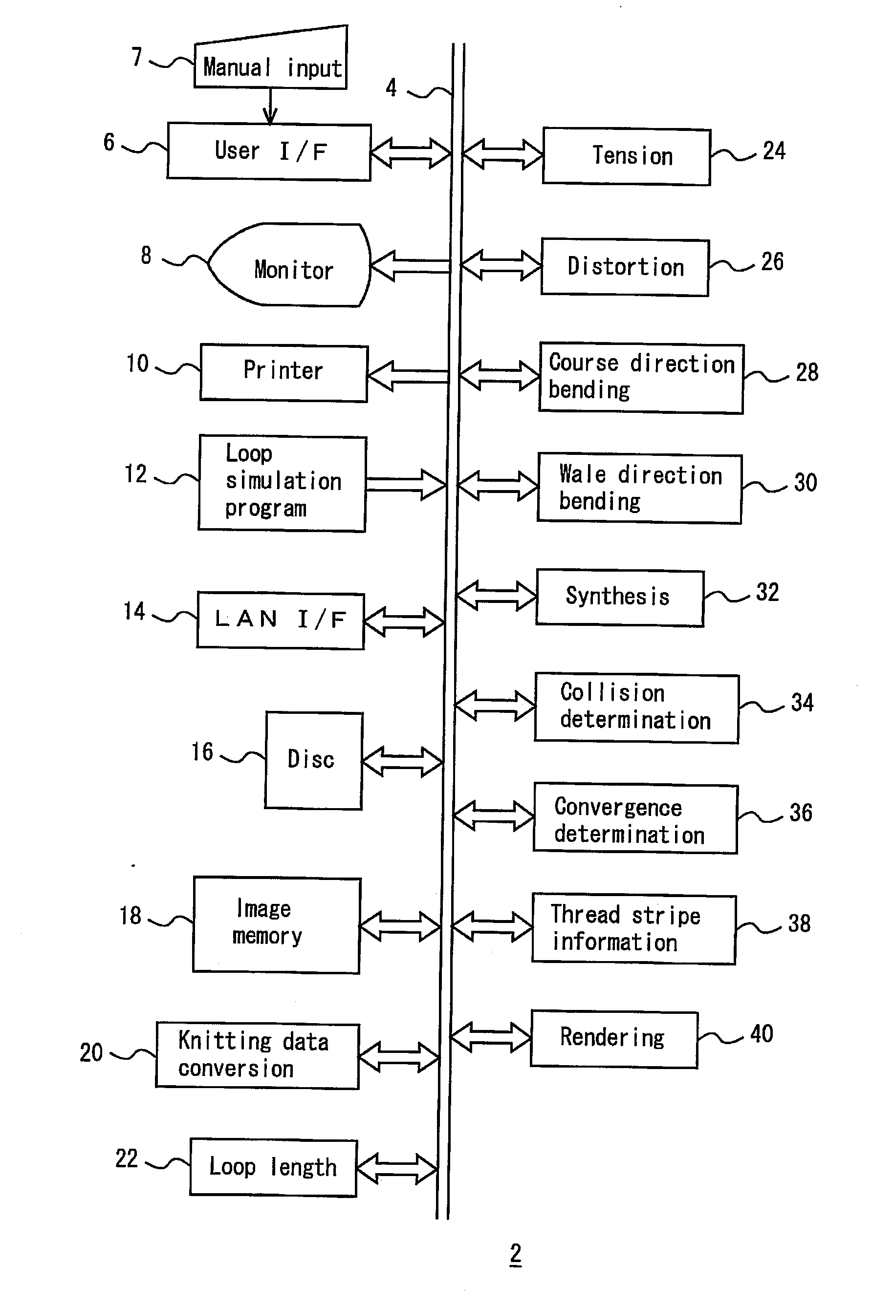
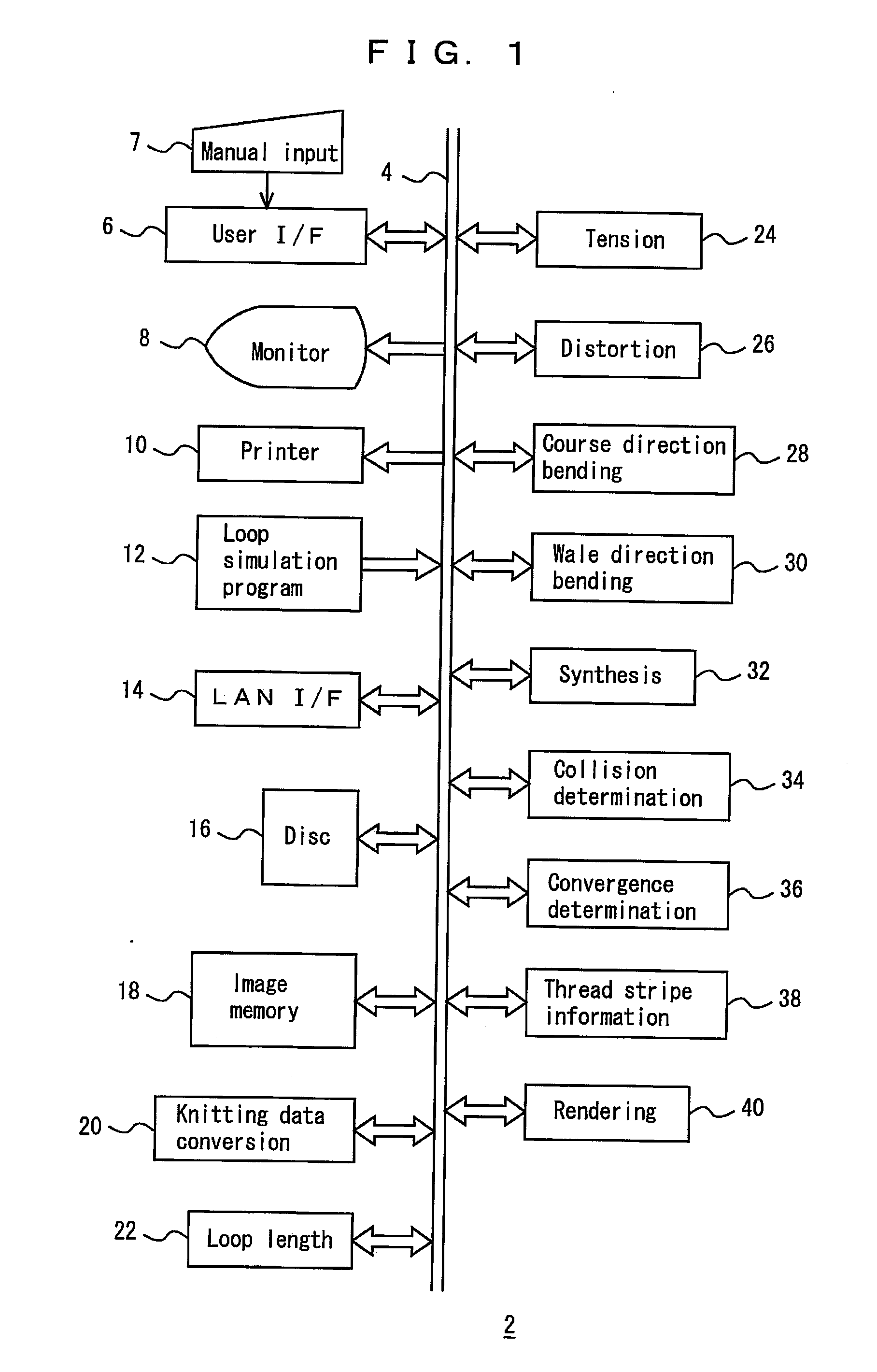
[0074]FIGS. 1 to 18 show an embodiment. In the drawings, 2 denotes a loop simulation apparatus, 4 denotes a bus for data, commands and so on, 6 denotes a user interface for inputting a knitted fabric design through manual input 7 using a stylus, a mouse, a track ball, a keyboard or similar. Further, the loop length of a stitch, the material of the thread, the shrinkage factor during finishing and so on are input into the user interface 6 from the manual input 7, as well as a standard value of the intersection angle between the course direction and the wale direction, or more precisely a standard value of an intersection angle between a line linking a subject stitch and an adjacent stitch in the course direction and a line linking the subject stitch and an adjacent stitch in the wale direction. Further, a standard value of an angle between two stitches on either side of an axis relating to a course direc...


PUM


Abstract

Shift of each stitch in a fabric is repeated and converged to eliminate the difference between distances to surrounding stitches and a default value, the deviation of an angle formed by a line connecting the right / left stitches and a line connecting the upper / lower stitches from 90°, the difference of an angle formed by the right / left stitches formed

Description

TECHNICAL FIELD[0001]The present invention relates to an apparatus for performing a realistic loop simulation of a knitted fabric, a loop simulation method, and a loop simulation program.BACKGROUND ART[0002]The present applicant has proposed that a loop simulation be performed by determining the position of stitches using an empirical rule based on the type of stitch, connection relationships with adjacent stitches and so on (Japanese Unexamined Patent Application 2005-120501). However, this method is problematic in that:[0003]the basis for the loop simulation is dependent on an empirical rule, and therefore ambiguous, and[0004]it is difficult to simulate a bulging knitted fabric such as a pin tuck pattern. Furthermore, it is difficult to simulate the curl at the ends of the knitted fabric.[0005]The latter two problems can be expressed together as difficulty in simulating the three-dimensional structure of the knitted fabric.DISCLOSURE OF THE INVENTION[0006]The basic objects of the ...

Claims


Application Information

Patent Timeline
IPC IPC(8): G06F19/00G06F17/50
CPCD04B37/02D04B35/00
Inventor TERAI, KOICHI
Owner SHIMA SEIKI MFG LTD
Learn More