Convenient sliding glass door intermediate lock system

a technology of intermediate locks and sliding glass doors, which is applied in the direction of building locks, construction fastening devices, construction, etc., can solve the problems of inconvenient use of such accessories, unsightly, and inability to readily accommodate the use of such accessories

Inactive Publication Date: 2010-06-17
CHEN KUEI YUNG
View PDF21 Cites 10 Cited by
  • Summary
  • Abstract
  • Description
  • Claims
  • Application Information

AI Technical Summary

Problems solved by technology

Such apertures or grooves can only be provided at the top or the bottom of the sliding glass door so the dead bolt must be attached at this location, making the use of such accessories very inconvenient to use, as well as unsightly.
Changes in the construction of sliding glass doors, such a the use of foamed thermoplastic extrusions for the rails and stiles of such doors, do not readily accommodate the use of such accessories due to the lack of a suitable physical structure in the rails to secure such accessories.

Method used


Image

  • Convenient sliding glass door intermediate lock system
  • Convenient sliding glass door intermediate lock system
  • Convenient sliding glass door intermediate lock system

Examples


Embodiment Construction

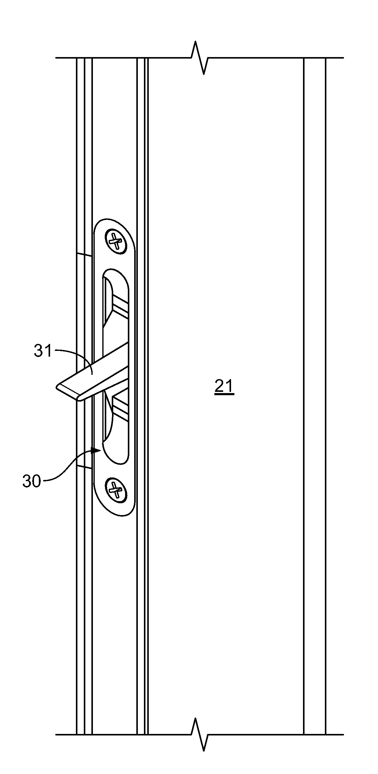
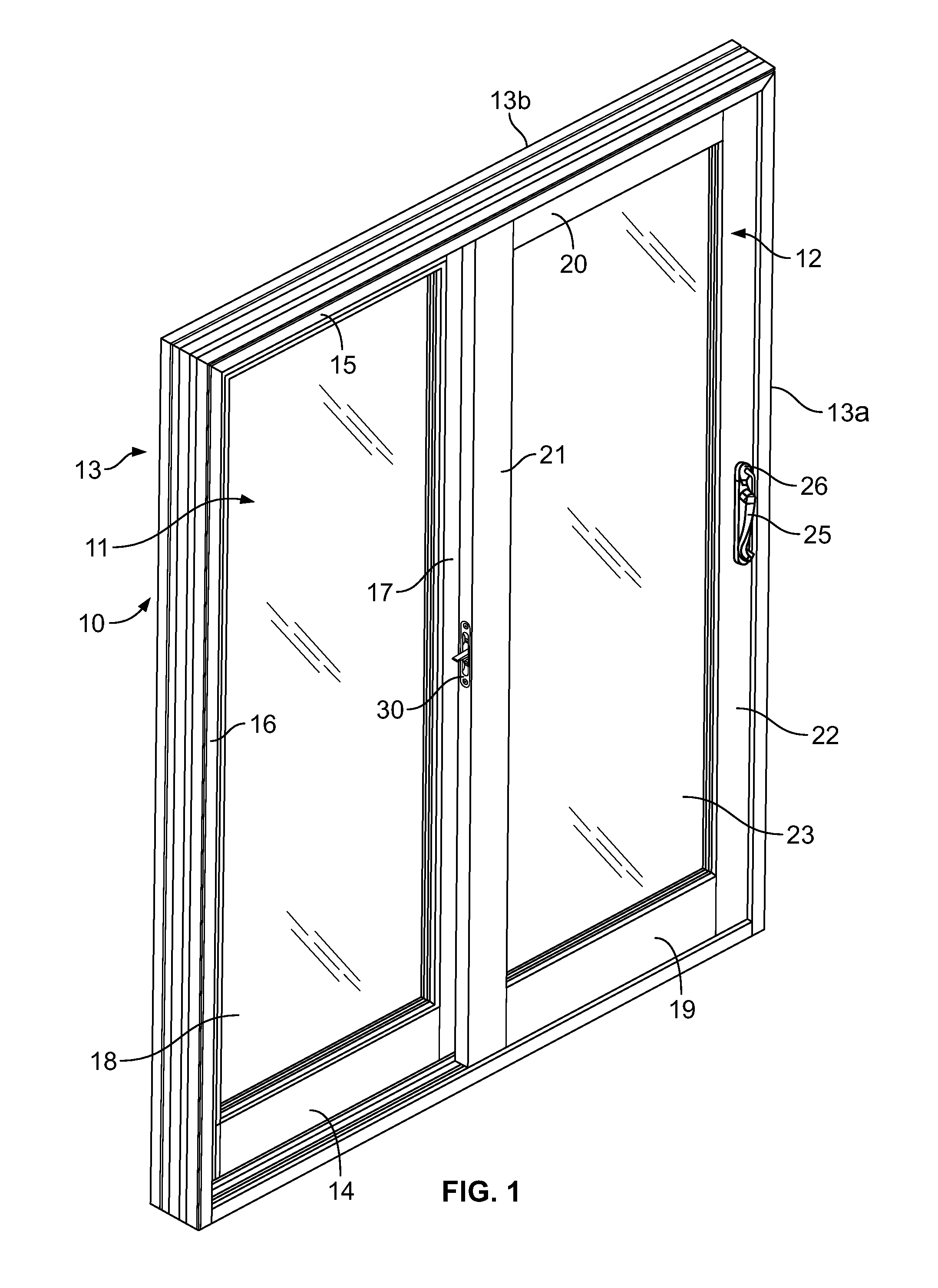
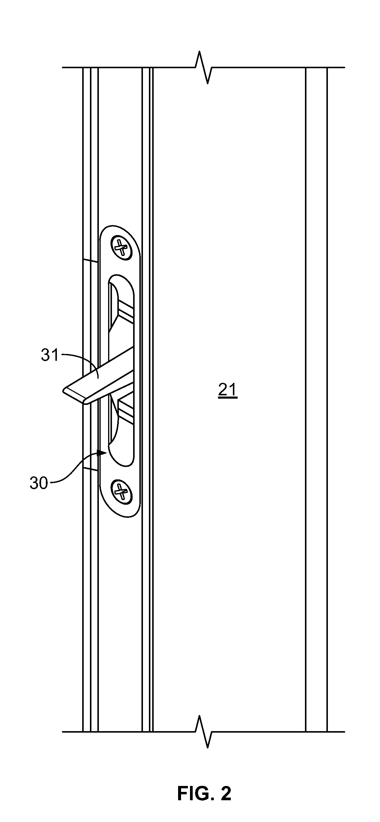
[0013]In FIG. 1 a sliding glass door unit 10 is illustrated, having a fixed glass panel 11 and a moveable glass panel 12 within its casement or frame 13. The fixed panel includes rails 14 and 15, the later being the top rail, and vertical stiles 16 and 17 assembled in a rectangular frame for supporting the glass panel 18. This panel is fixedly secured in the casement so there is no relative movement of this door panel relative to the casement.

[0014]The other glass panel 12 also includes rails 19 and 20, the latter being the top rail, and vertical stiles 21 and 22 assembled in a rectangular frame for supporting its glass panel 23. Unlike the fixed panel 11, this panel has rollers (not shown) in the bottom rail 19 so that the panel can be moved or slide between the vertical members of the casement 13.

[0015]As is typical with sliding glass doors, stile 22 of the moveable / slidable panel 12 includes a handle 25 and a lock 26 which cooperate with a typical latching structure (not shown) i...


PUM


Abstract

In a sliding glass door system, having a stationary panel and a movable panel within a door casement, the improvement of incorporating an independent locking system centrally located in the vertical stile of the movable panel remote from the conventional door lock for this panel includes an operating lever mounted in the stile so one end thereof is accessible, a vertical oriented locking bolt connected to the lever for reciprocal movement through manipulation of the lever, and a plurality of apertures in the top track of casement for the movable panel whereby the lever can be manipulated to insert the distal end of vertical locking bolt into selected apertures to lock the panel in selected intermediate positions or to remove the distal end the vertical locking bolt from such apertures to release the panel. In the preferred embodiment the connection of the lever to locking bolt and the bolt are located inside a channel in the associated stile to maintain the aesthetics of the door. Typically the lever is mounted in middle of the associated stile for added safety and convenience.

Description

BACKGROUND[0001]Sliding glass doors are widely used in residential and commercial buildings. Typically the doors can only be locked in the closed position. However there are dead bolt-type accessories that can be purchased at hardware and like stores which can be attached to a moveable part (door panel) of a sliding glass door, typically by screws, see e.g., U.S. Pat. No. 6,655,720. Such accessories require apertures or grooves at the top or bottom of door casement for engagement by the lock bolt, for each intermediate position elected between an open and closed position. Such apertures or grooves can only be provided at the top or the bottom of the sliding glass door so the dead bolt must be attached at this location, making the use of such accessories very inconvenient to use, as well as unsightly.[0002]Changes in the construction of sliding glass doors, such a the use of foamed thermoplastic extrusions for the rails and stiles of such doors, do not readily accommodate the use of ...

Claims


Application Information

Patent Timeline
Patent Type & Authority Applications(United States)
IPC IPC(8): E05B65/08
CPCE05C17/60Y10T70/519
Inventor CHEN, KUEI YUNG
Owner CHEN KUEI YUNG
Why Eureka
Try Eureka