
User-friendlier interfaces for a camera

a user-friendly interface and camera technology, applied in the direction of camera focusing arrangement, printers, instruments, etc., can solve the problems of non-optimal placement, inability to take pictures, so as to improve the auto focus capability of the camera, improve the user interface, and improve the effect of natural and fast processing

Active Publication Date: 2010-07-01
CUTTING EDGE VISION
View PDF15 Cites 9 Cited by
  • Summary
  • Abstract
  • Description
  • Claims
  • Application Information

AI Technical Summary

Benefits of technology

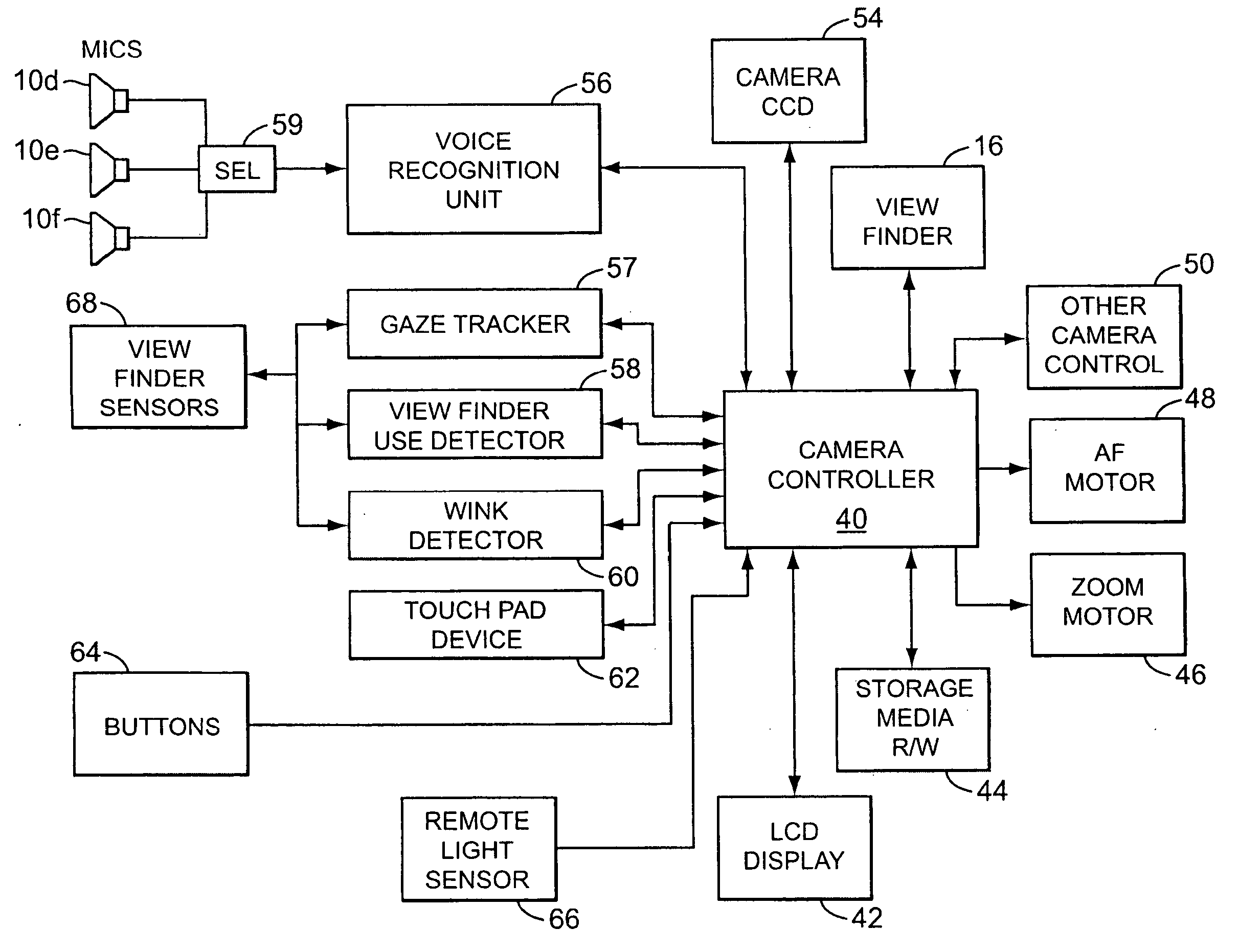
[0005]A self-contained camera system, according to various aspects of the present invention, includes voice recognition wherein multiple different vocalizations can be recognized and wherein some such recognized vocalizations can be associated with the same camera command. Another aspect of the invention provides for multiple microphones disposed on or in the camera system body and be operable so that the user can be anywhere around the camera system and be heard by the camera system equally well. According to other aspects of the present invention, the camera system viewfinder includes gaze tracking ability and in exemplary preferred embodiments, gaze tracking is used alone or in combination with other aspects of the invention to, for example, manipulate menus, improve picture taking speed, or improve the auto focus capability of the camera. Other aspects of the present invention, such as the addition of touchpad technology and gesture recognition provide for a improved and more natural user interface to the camera system.

Problems solved by technology

This is cumbersome and leads to nontrivial problems.
Additionally, many who might like to be included into a shot find themselves not able to be because they have to take the picture and it is simply too much trouble to set up for a shutter-delayed photograph.
One such problem is that in self portrait mode, the camera may snap the picture while the user is uttering the command.
Another defect is that the microphone coupled to the voice recognition unit is usually mounted on the back of the camera.
This placement is non-optimal when the user is in front of the camera as when taking a self portrait.
Still another problem with prior art voice activated cameras is that they associate one vocalization or utterance to one camera operation.
This is overly constraining, unnatural, and significantly reduces the utility of adding voice recognition to the camera.

Method used


Image

  • User-friendlier interfaces for a camera
  • User-friendlier interfaces for a camera
  • User-friendlier interfaces for a camera

Examples


Embodiment Construction

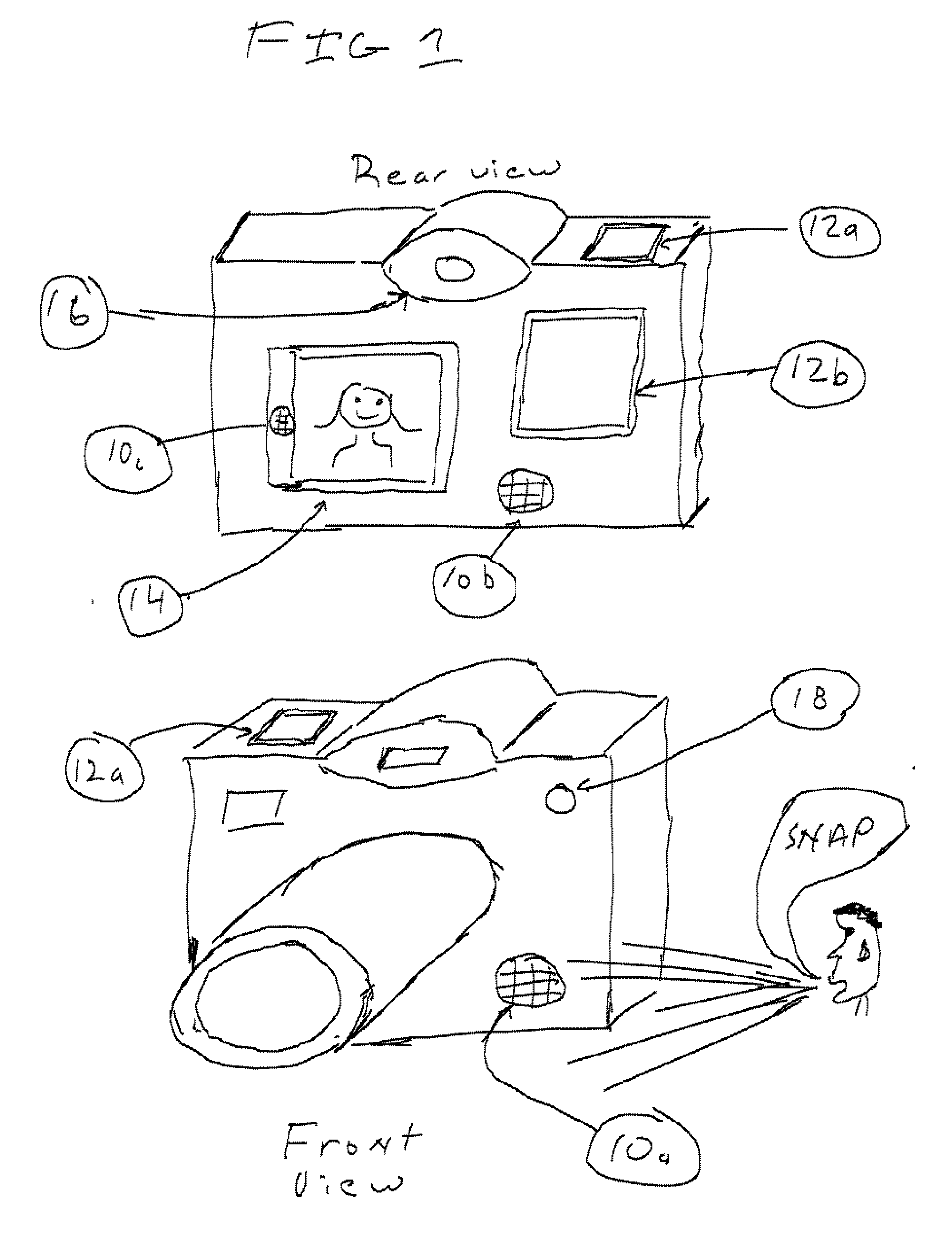
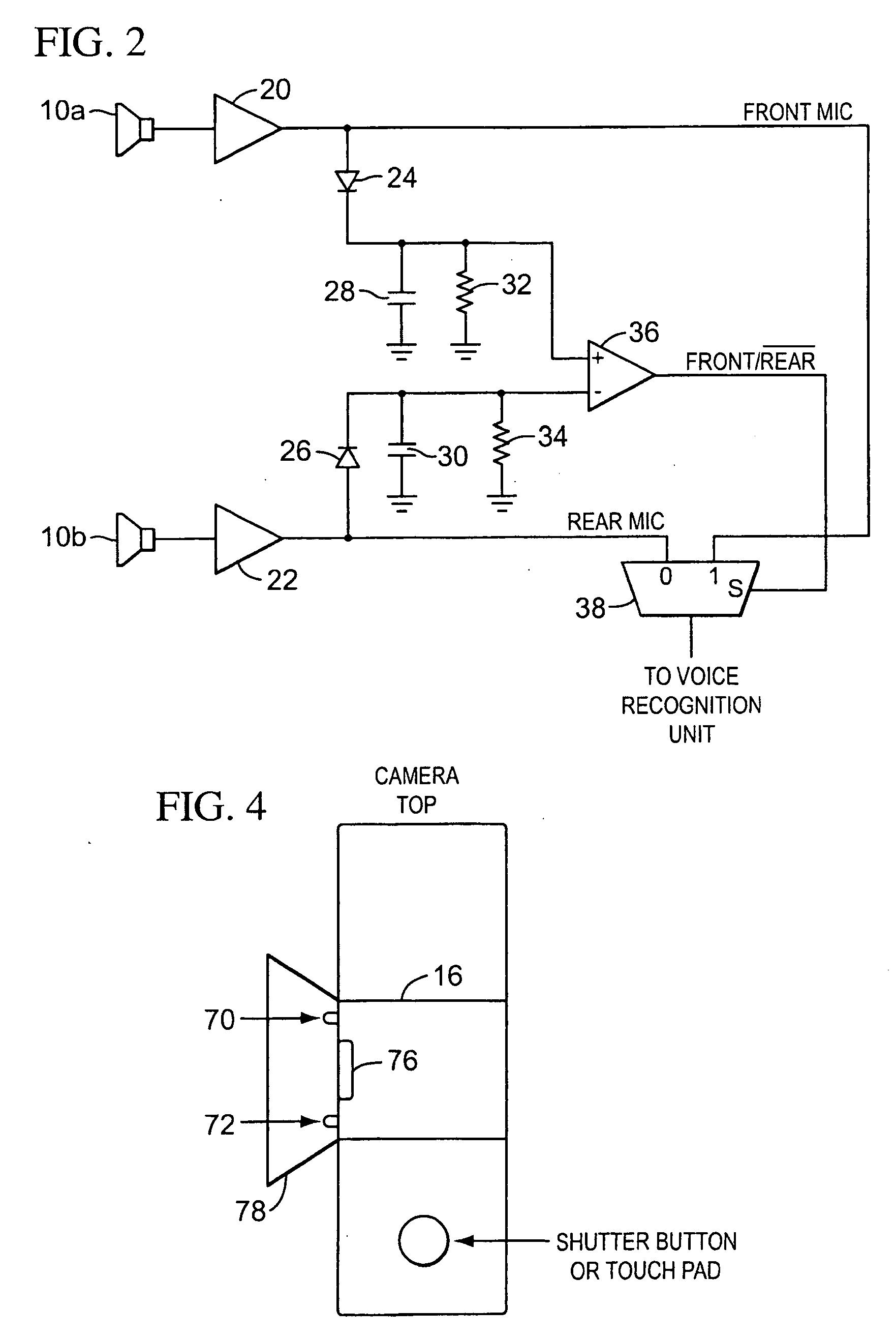
[0012]One aspect of the present invention solves several of the problems of the prior art voice recognition cameras in that this aspect provides for more than one microphone to be the source to the recognition unit. With reference to FIG. 1, this aspect of the present invention provides for at least two microphones to be used, one microphone, 10b, placed on the back of the camera and one microphone, 10a, placed on the front, either of which can receive voice commands. In a first preferred embodiment of this aspect of the invention, a detection device determines which microphone is to be used as the input to the recognition unit based upon the strength of the voice signal or sound level received by each of the microphones. In another preferred embodiment, the outputs of the microphones are combined as the input to the voice recognition unit (also referred to as the voice recognition subsystem or the recognizer subsystem) 56. In still another embodiment, the user can select which micr...


PUM


Abstract

A camera system, including voice recognition, one or multiple microphones, gaze tracking, touch sensitive inputs and others. The voice recognition unit is operable for, among other things, receiving multiple different voice commands, recognizing the vocal commands, associating the different voice commands to one camera command and controlling at least some aspect of the digital camera operation in response to these voice commands. The gaze tracking unit is operable for, among other things, determining the location on the viewfinder image that the user is gazing upon. One aspect of the touch sensitive inputs provides that the touch sensitive pad is mouse-like and is operable for, among other things, receiving user touch inputs to control at least some aspect of the camera operation. Another aspect of the disclosed invention provides for gesture recognition to be used to interface with and control the camera system.

Description

CROSS REFERENCE TO RELATED APPLICATIONS[0001]This application is a divisional of application Ser. No. 11 / 163,391, filed Oct. 17, 2005, which is herein incorporated by reference.BACKGROUND OF THE INVENTION[0002]Digitally-based and film-based cameras abound and are extremely flexible and convenient. One use for a camera is in the taking of self portraits. Typically, the user frames the shot and places the camera in a mode whereby when the shutter button is depressed; the camera waits a predetermined time so that the user may incorporate himself back into the shot before the camera actually takes the picture. This is cumbersome and leads to nontrivial problems. Sometimes the predetermined delay time is not long enough. Other times, it may be too long. For participates who are in place and ready to have their picture taken, especially children, waiting with a smile on their face for the picture to be snapped by the camera can seem endless even if it is just a few seconds long. Additiona...

Claims


Application Information

Patent Timeline
Patent Type & Authority Applications(United States)
IPC IPC(8): G03B17/00G03B13/00
CPCG03B17/02H04N1/2112G03B31/06H04N5/232H04N5/23293H04N5/23203H04N1/00244G06F3/041G10L15/22G10L2015/223H04N5/23206H04N5/23222G10L17/22H04N1/00212H04N1/00095H04N2201/0084H04N5/23216G03B13/02H04N5/23219H04M3/42204H04N1/00209H04N1/00204H04N5/2257G03B29/00H04N23/661H04N23/631H04N23/66H04N23/57H04N23/62H04N23/64H04N23/611
Inventor KONICEK, JEFFREY C.
Owner CUTTING EDGE VISION
Learn More