Sterile surgical tray

a surgical tray and sterile technology, applied in the field of surgical trays, can solve the problems of unfavorable interaction between surgeon and assistant, and achieve the effect of improving the efficiency of the interaction

Inactive Publication Date: 2010-07-08
DOHENY EYE INST
View PDF44 Cites 87 Cited by
  • Summary
  • Abstract
  • Description
  • Claims
  • Application Information

AI Technical Summary

Benefits of technology

[0027]For purposes of this summary, certain aspects, advantages, and novel features of the invention are described herein. It is to be understood that not necessarily all such advantages may be achieved in accordance with any particular embodiment of the invention. Thu

Problems solved by technology

However, with the present trend of surgeries moving away from hospital and into ambulatory surgery centers (ASCs) and even into a doctor's own office, coupled with reduced reimbursements for surgical procedures, there is a need to allow surgeons to perform surgery with little o

Method used


Image

  • Sterile surgical tray
  • Sterile surgical tray
  • Sterile surgical tray

Examples


example process

Flow

[0116]FIG. 15 is a flow diagram of a process executed by the processing unit 1446 of an independent surgical center in accordance with an embodiment of the invention.

[0117]In some embodiments, the process of FIG. 15 represents the process which is performed by the processing unit housed or received in the sterile surgical tray as described herein. In some embodiments of the invention, the process may be performed in another instrument or component of the system, based on where the processing unit is located in the system. In some embodiments, the system may include multiple processing units, and the process of FIG. 15 may be performed by one or more of the multiple processing units.

[0118]In block 611, the process receives a signal from an instrument in communication with the independent surgical center. In the embodiment, the tray may receive the signals from an instrument through a wired connection, for example, the handpiece, or may receive the signals from an instrument throu...


PUM

PropertyMeasurementUnit
Shapeaaaaaaaaaa
Energyaaaaaaaaaa
Vacuumaaaaaaaaaa

Abstract

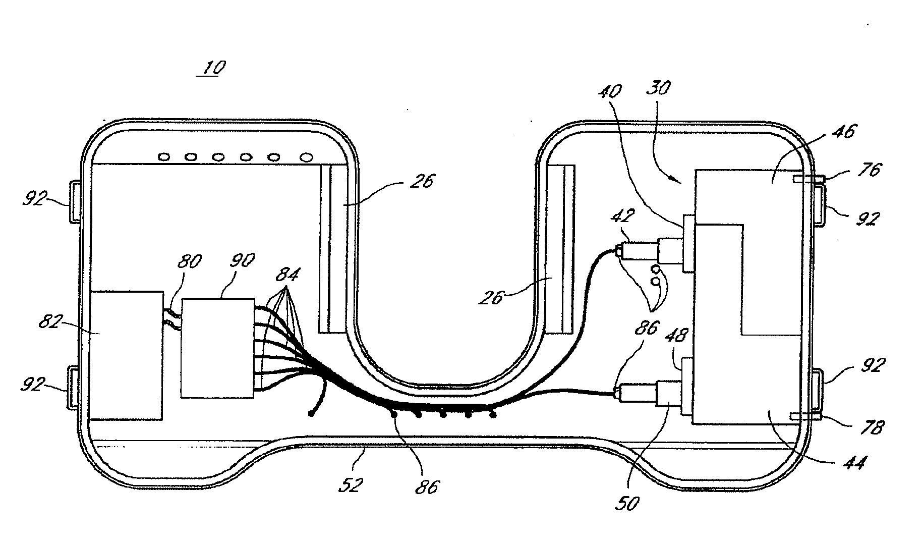
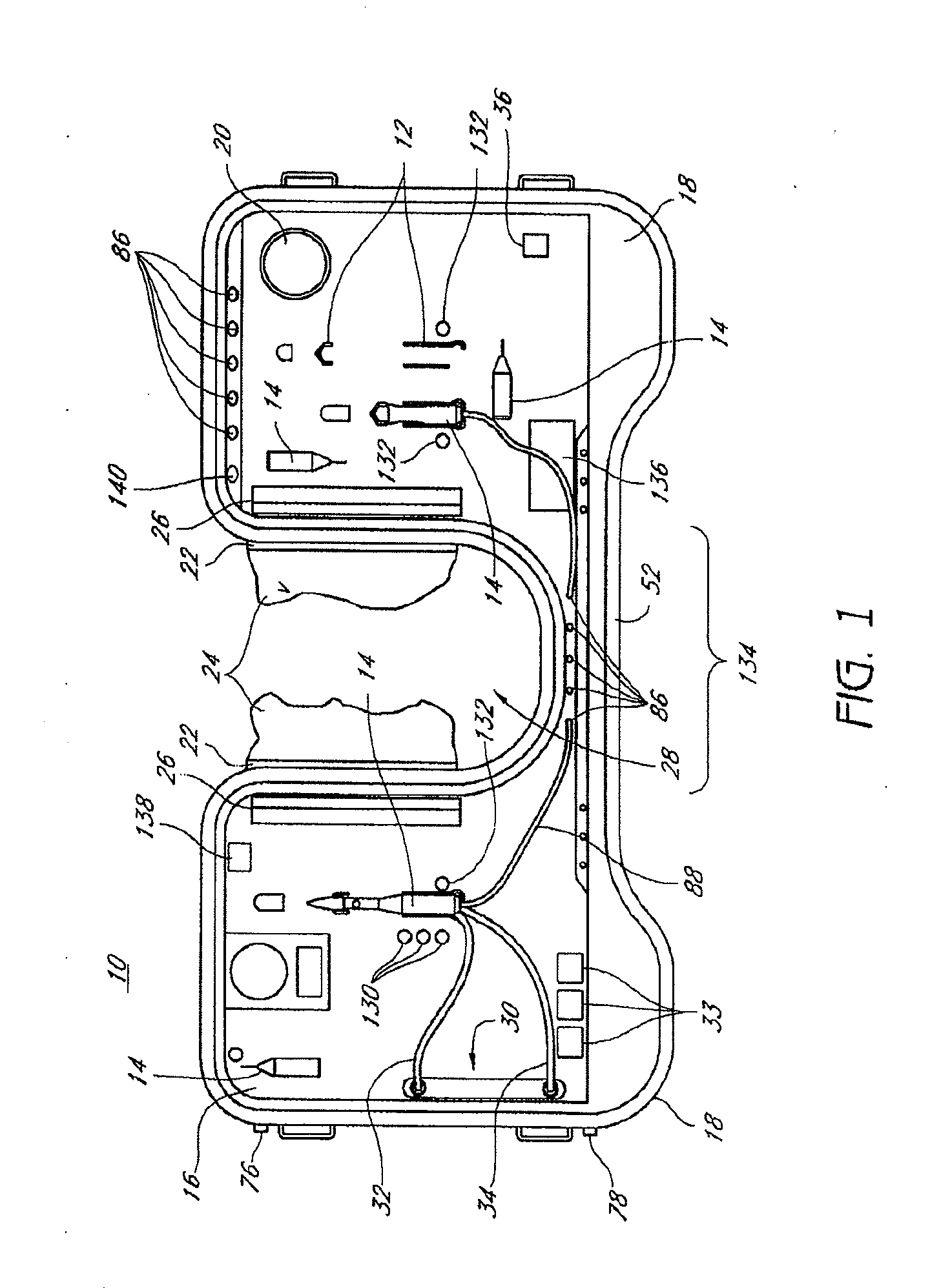
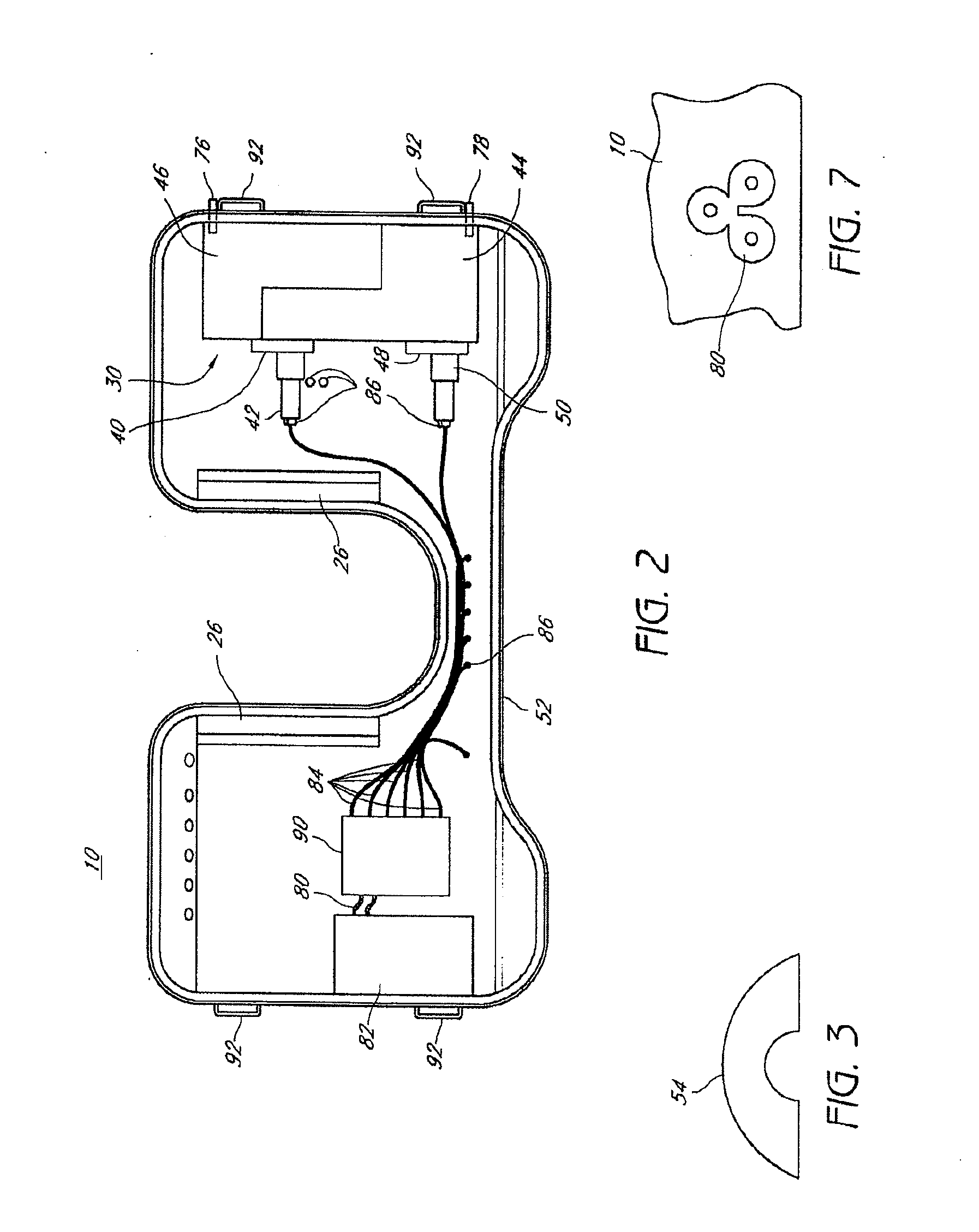
A sterile surgical tray includes structure for receiving a plurality of surgical instruments. The sterile surgical tray also may include electrical input and output connectors attached to tray.

Description

CROSS-REFERENCE TO RELATED APPLICATIONS[0001]This application is a continuation-in-part application of U.S. application Ser. No. 12 / 256,420 filed Oct. 22, 2008, and titled STERILE SURGICAL TRAY, which is a continuation-in-part application of U.S. application Ser. No. 12 / 107,038 filed Apr. 21, 2008 and titled INDEPENDENT SURGICAL CENTER, which claims the benefit of U.S. Provisional Application No. 60 / 925,546 filed Apr. 20, 2007, and titled INDEPENDENT SURGICAL CENTER INCLUDING A PORTABLE VITRECTOMY HANDPIECE AND INFUSION / ASPIRATION CASSETTE. U.S. application Ser. No. 12 / 256,420 is also a continuation-in-part application of U.S. application Ser. No. 12 / 107,052 filed Apr. 21, 2008, and titled PERSONAL SURGICAL CENTER, which claims the benefit of U.S. Provisional Application No. 60 / 925,562 filed Apr. 20, 2007, and titled PERSONAL SURGICAL CENTER. U.S. application Ser. No. 12 / 256,420 is also a continuation-in-part application of U.S. application Ser. No. 12 / 106,962 filed Apr. 21, 2008, a...

Claims


Application Information

Patent Timeline
IPC IPC(8): G05D7/06A61B19/02G06F1/26G06F13/00G06F17/00F16L3/00E03B5/00A61B17/00
CPCA61M2205/3561A61B2017/00544A61F9/00736A61B2017/00734A61B19/0271A61B2019/025A61B19/38A61B2017/00973A61M2205/505A61F9/00763A61B2017/00225A61M3/0262A61B2019/0278A61M2205/123A61M2205/3553A61B19/5202A61B2019/448A61B90/30A61B50/13A61B2050/3008A61B90/40A61B90/98Y10T137/8376Y10T137/86035A61B50/33A61M3/022A61M3/0254A61M1/77A61M3/0201A61M1/72A61M1/80A61B2017/00539A61B17/00
Inventor HUMAYUN, MARKDEBOER, CHARLESMCCORMICK, MATTHEWBHADRI, PRASHANTCICCHELLA, JOELKERNS, RALPH
Owner DOHENY EYE INST
Why Eureka
Try Eureka