Mechanical resonating structures including a temperature compensation structure

a technology of mechanical resonating structure and temperature compensation structure, which is applied in piezoelectric/electrostrictive/magnetostrictive devices, piezoelectric/electrostriction/magnetostriction machines, electrical apparatuses, etc., can solve problems such as material expansion and contraction, change in material stiffness, and variation in vibrational characteristics

Active Publication Date: 2010-07-22
ANALOG DEVICES INC
View PDF39 Cites 54 Cited by
  • Summary
  • Abstract
  • Description
  • Claims
  • Application Information

AI Technical Summary

Problems solved by technology

Such conditions and variations can cause material expansion and contraction, as well as changes in material stiffness.
This can result in a variation in vibrational characteristics (e.g., resonating frequency) across the temperature range.
These effects also can lead to increased noise, reduction in bandwidth, deterioration of signal quality and can, in general, create stability problems in devices.

Method used


Image

  • Mechanical resonating structures including a temperature compensation structure
  • Mechanical resonating structures including a temperature compensation structure
  • Mechanical resonating structures including a temperature compensation structure

Examples


example

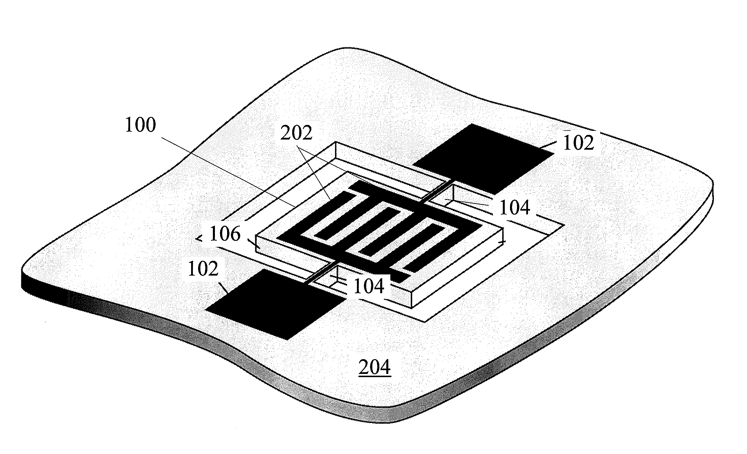
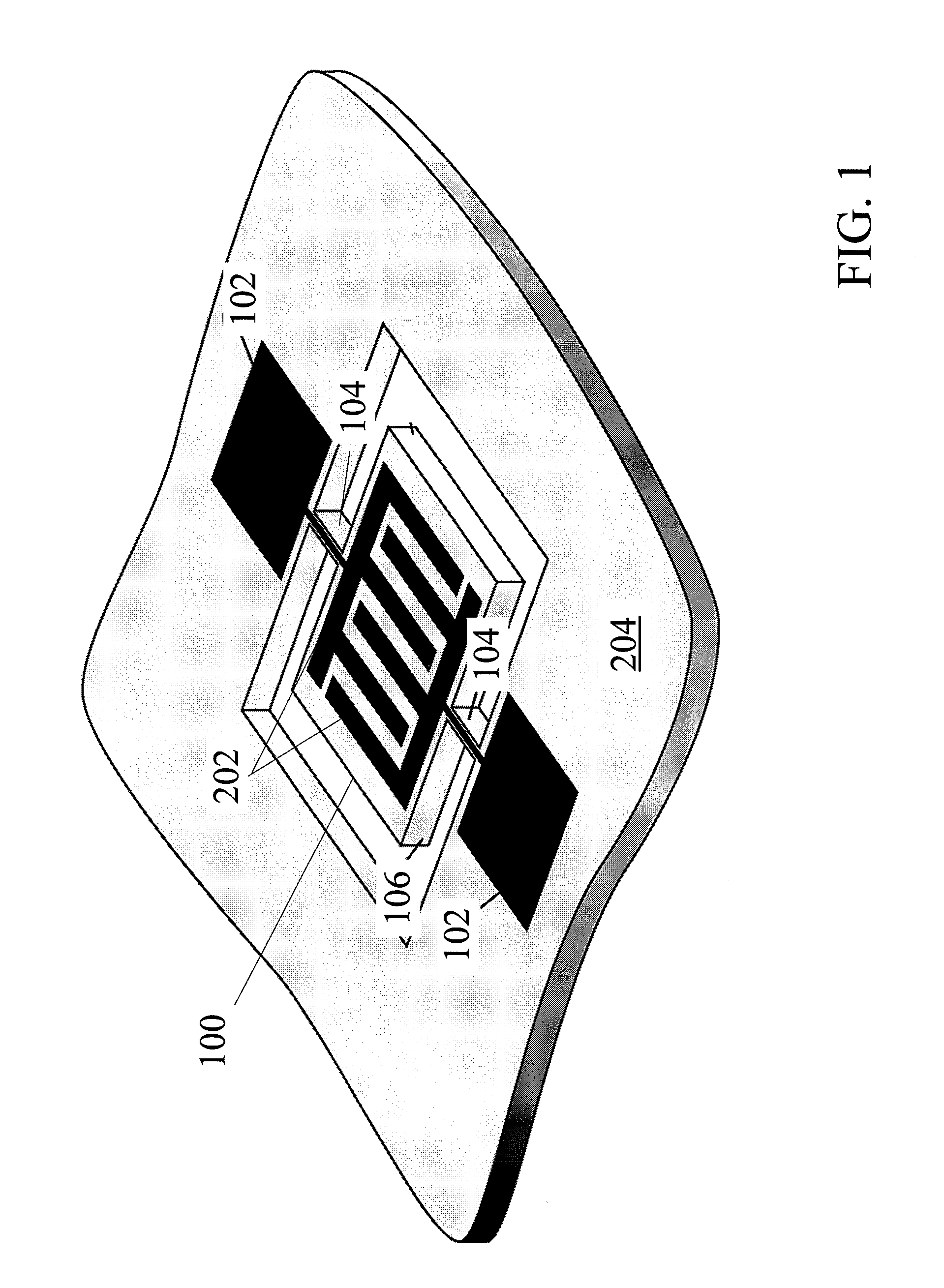
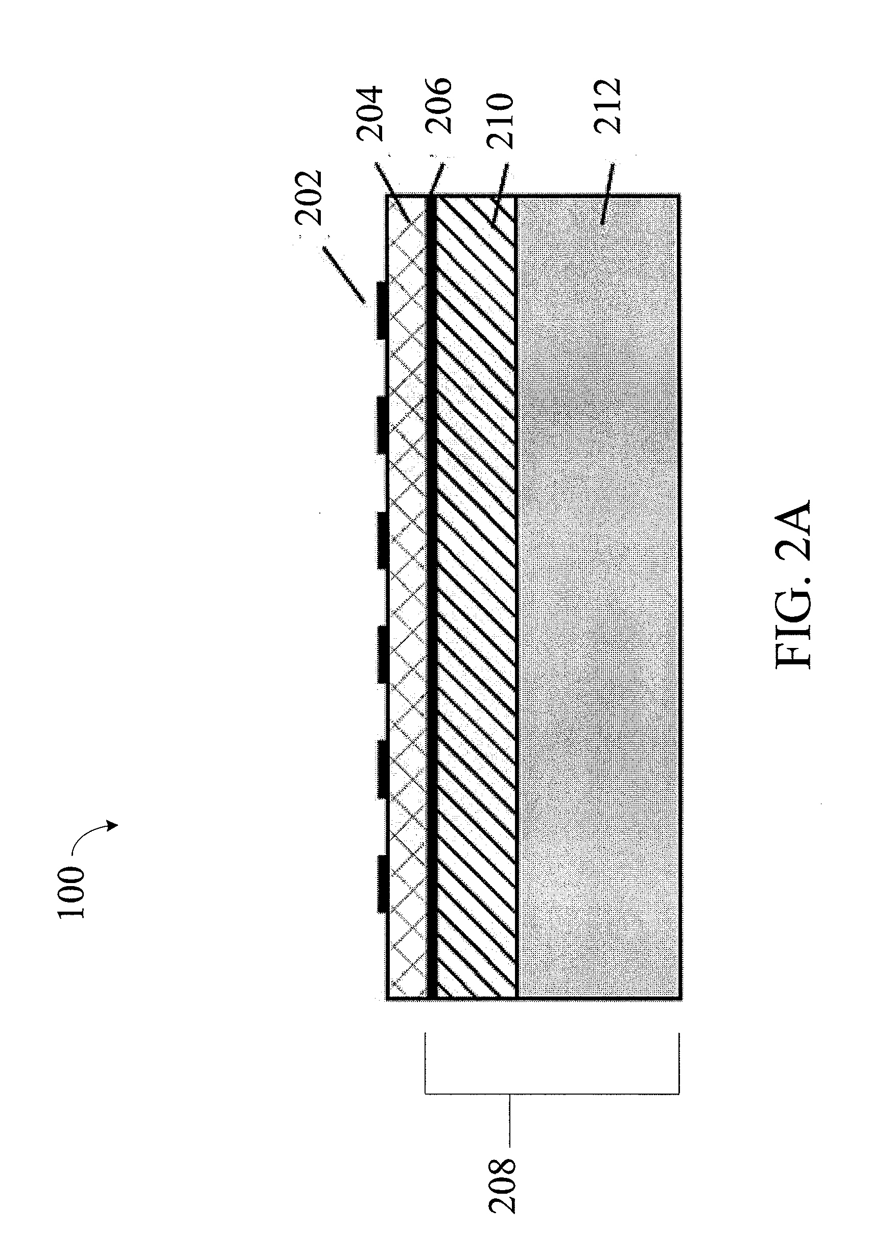
[0081]The following is an example that illustrates that the TCF of a mechanical resonating structure can be controlled according to the methods described herein with reference to FIGS. 3A-3J. In this example, layers 210, 214 are formed of SiO2 and layer 212 is formed of Si.

[0082]FIG. 3E is an indicator of how the TCF varies as a function of temperature. Specifically, FIG. 3E shows a graph of the normalized frequency variation (Δf / f) versus temperature. The TCF corresponds to the slope of this curve. As noted above, the active layer can have a negative TCF, and SiO2 can have a positive TCF for a specified range of temperatures.

[0083]FIG. 3A shows an example of a mechanical resonating structure with an active layer (e.g., AlN), a bottom electrode, a Si layer 212 and no SiO2 layers. This structure has a negative TCF of approximately −30 ppm / K (illustrated by line A in FIG. 3E). FIG. 3B shows an example of a mechanical resonating structure with a Si layer placed between two SiO2 layers ...


PUM


Abstract

Mechanical resonating structures are described, as well as related devices and methods. The mechanical resonating structures may have a compensating structure for compensating temperature variations.

Description

RELATED APPLICATIONS[0001]The present application claims the benefit of U.S. Provisional Patent Application Ser. No. 61 / 138,171, filed Dec. 17, 2008 and titled “Mechanical Resonating Structures Including a Temperature Compensation Structure,” which application is hereby incorporated by reference herein in its entirety.FIELD OF INVENTION[0002]The invention relates generally to mechanical resonating structures, and more particularly, to mechanical resonating structures having a temperature compensation structure, as well as related devices and methods.BACKGROUND OF INVENTION[0003]Mechanical resonators are physical structures that are designed to vibrate at high frequencies. Such resonators may be incorporated into a variety of devices such as timing oscillators, mass sensors, gyros, accelerometers, switches, and electromagnetic fuel sensors, amongst others.[0004]During use, mechanical resonators, and the devices which incorporate the same, may be exposed to different temperature condi...

Claims


Application Information

Patent Timeline
Patent Type & Authority Applications(United States)
IPC IPC(8): H03H9/17
CPCH03H9/02102H03H9/02228H03H9/02448H03H9/02574H03H9/02834
Inventor KUYPERS, JAN H.CHEN, DAVID M.GAIDARZHY, ALEXEIZOLFAGHARKHANI, GUITI
Owner ANALOG DEVICES INC
Why Eureka
Try Eureka