Battery system with battery holders

a battery system and battery holder technology, applied in the field of battery systems, can solve the problems of increasing the outline of the battery unit, making the tight connection of the battery unit with its periphery even more difficult, and the difficulty of retaining the battery block at the periphery, so as to achieve the effect of reducing the outline of the battery system and retaining the battery block more robustly

Active Publication Date: 2010-07-29
SANYO ELECTRIC CO LTD
View PDF23 Cites 20 Cited by
  • Summary
  • Abstract
  • Description
  • Claims
  • Application Information

AI Technical Summary

Benefits of technology

[0012]The battery system described above can solidly retain many battery holders with the rows of upper connecting cylinders and lower connecting cylinders. Further, where upper connecting cylinders are disposed, a region with no protrusions is established below those connecting cylinders. Where lower connecting cylinders are disposed, a region with no protrusions is established above those connecting cylinders. Consequently, by disposing b

Problems solved by technology

If many connecting bolts are used to tightly connect the battery units, the battery unit outline (footprint) becomes larger.
In addition, a battery system of this structure has the drawback that because connecting bolts are disposed at the interior of the battery units, it is difficult to join the battery units with their peripheries tightly connected.
In particular, if connecting bolts are strongly tightened to solidly attach the battery units, battery unit center regions can indent making tight connection at the peripheries even more difficult.
This drawback becomes more serious when many batteries are disposed in a single plane and

Method used


Image

  • Battery system with battery holders
  • Battery system with battery holders
  • Battery system with battery holders

Examples


Embodiment Construction

)

[0026]The following describes embodiments of the present invention based on the figures.

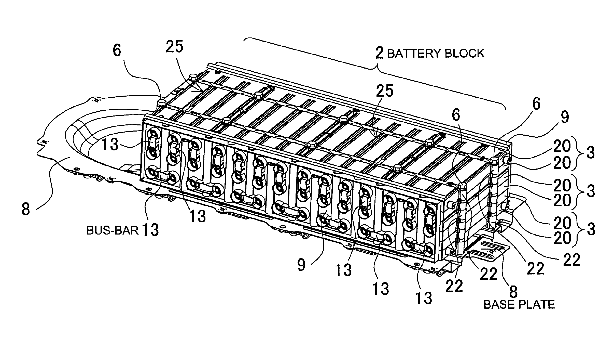
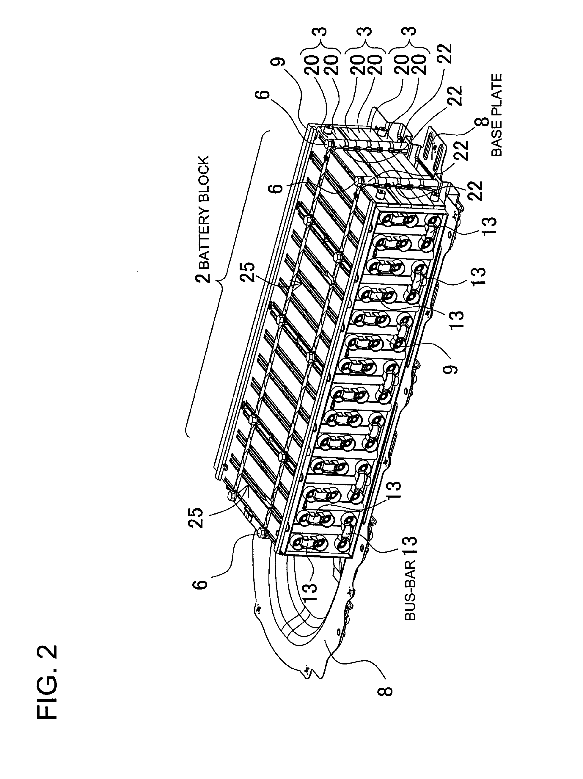
[0027]The battery system shown in FIGS. 2-5 is used as a power source apparatus in a hybrid car, and it supplies power to an electric motor that drives the vehicle. However, the battery system of the present invention is not limited to hybrid car power source apparatus applications. The battery system of the present invention can also be used in electrically powered vehicles such as electric automobiles (electric vehicles) or plug-in hybrid cars, or in other power source apparatus applications that require a large output.

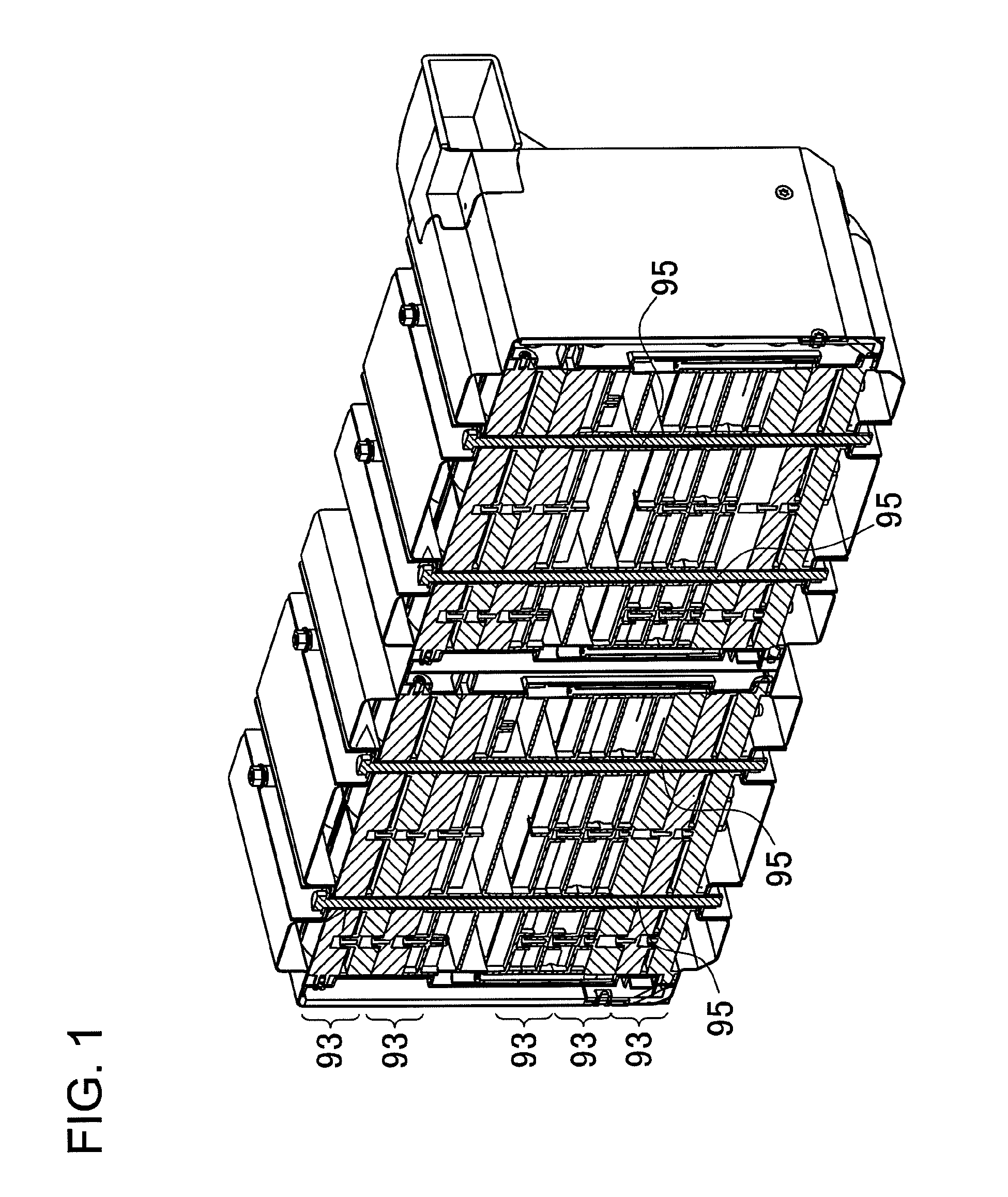
[0028]As shown in the figures, six levels of battery holders 20 are retained in a stack to form a battery block 2. Since batteries 1 are disposed between a pair of battery holders 20, two battery holder 20 levels make up a single battery unit 3. Consequently, this battery system has six levels of battery holders 20 and three levels of battery units 3 held in a stacked configurat...


PUM


Abstract

The connecting bolts 5 are inserted through the connecting cylinders 21 to hold a plurality of battery holders 20 in the stacked configuration and form a battery block 2. The battery holder 20 connecting cylinders 21 are disposed at a plurality of locations on the perimeter of the battery block 2, and are disposed in straight-lines to form rows of partial-stack connecting cylinders 4 on battery holders 20 stacked in two levels or more, but not on the entire stack of battery holders 20. Connecting bolts 5 are inserted through each row of partial-stack connecting cylinders 4 to hold the connecting cylinders 21 that make up each row of partial-stack connecting cylinders 4 in a stacked configuration, and retain the battery holders 20 in a stacked configuration as a battery block 2.

Description

BACKGROUND OF THE INVENTION[0001]1. Field of the Invention[0002]The present invention relates to a battery system with a plurality of batteries disposed between a plurality of stacked battery holders, and in particular to a battery system with a plurality of stacked battery holders connected and held in place by bolts.[0003]2. Description of the Related Art[0004]As a battery system housing many batteries capable of being charged, a configuration has been developed that has battery units stacked in a plurality of levels with each battery unit housing many batteries (refer to Japanese Laid-Open Patent Publication 2008-110693).[0005]In this battery system, the number of batteries inside can be increased by increasing the number of levels of stacked battery units. Since this structure can adjust the number of batteries by adjusting the number of battery unit levels, it is suitable for use in applications such as in hybrid cars where the required output is different for different types o...

Claims


Application Information

Patent Timeline
IPC IPC(8): B60K6/20H01M2/10B60K6/448H01M50/213H01M50/227H01M50/264H01M50/505H01M50/51H01M50/512H01M50/522
CPCH01M2/1077H01M2/206H01M10/625H01M10/6563H01M10/647H01M10/6557H01M10/643H01M10/613Y02E60/10H01M50/522H01M50/213H01M50/264H01M50/512H01M50/51H01M50/505H01M50/227
Inventor KOMAKI, TSUYOSHI
Owner SANYO ELECTRIC CO LTD
Why Eureka
Try Eureka