Reduction of Tip Vortex and Wake Interaction Effects in Energy and Propulsion Systems

a technology of energy and propulsion system and interaction effect, applied in the field of plasma actuation, can solve problems such as structural problems, noise, excitation phenomena, source of aerodynamic loss, noise and excitation,

Active Publication Date: 2010-07-29
GENERAL ELECTRIC CO
View PDF16 Cites 17 Cited by
  • Summary
  • Abstract
  • Description
  • Claims
  • Application Information

AI Technical Summary

Benefits of technology

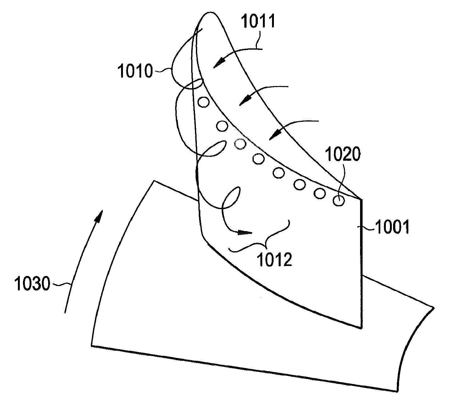
[0006]An embodiment of the invention includes an airfoil. The airfoil includes a plasma actuation surface integrated onto the airfoil surface. On the airfoil, the plasma actuation surface is configured

Problems solved by technology

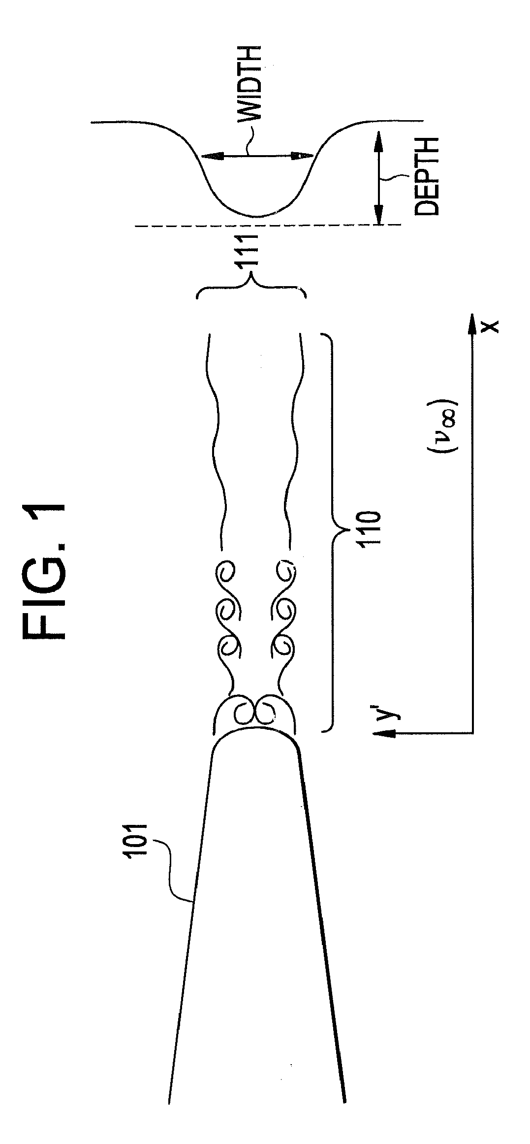
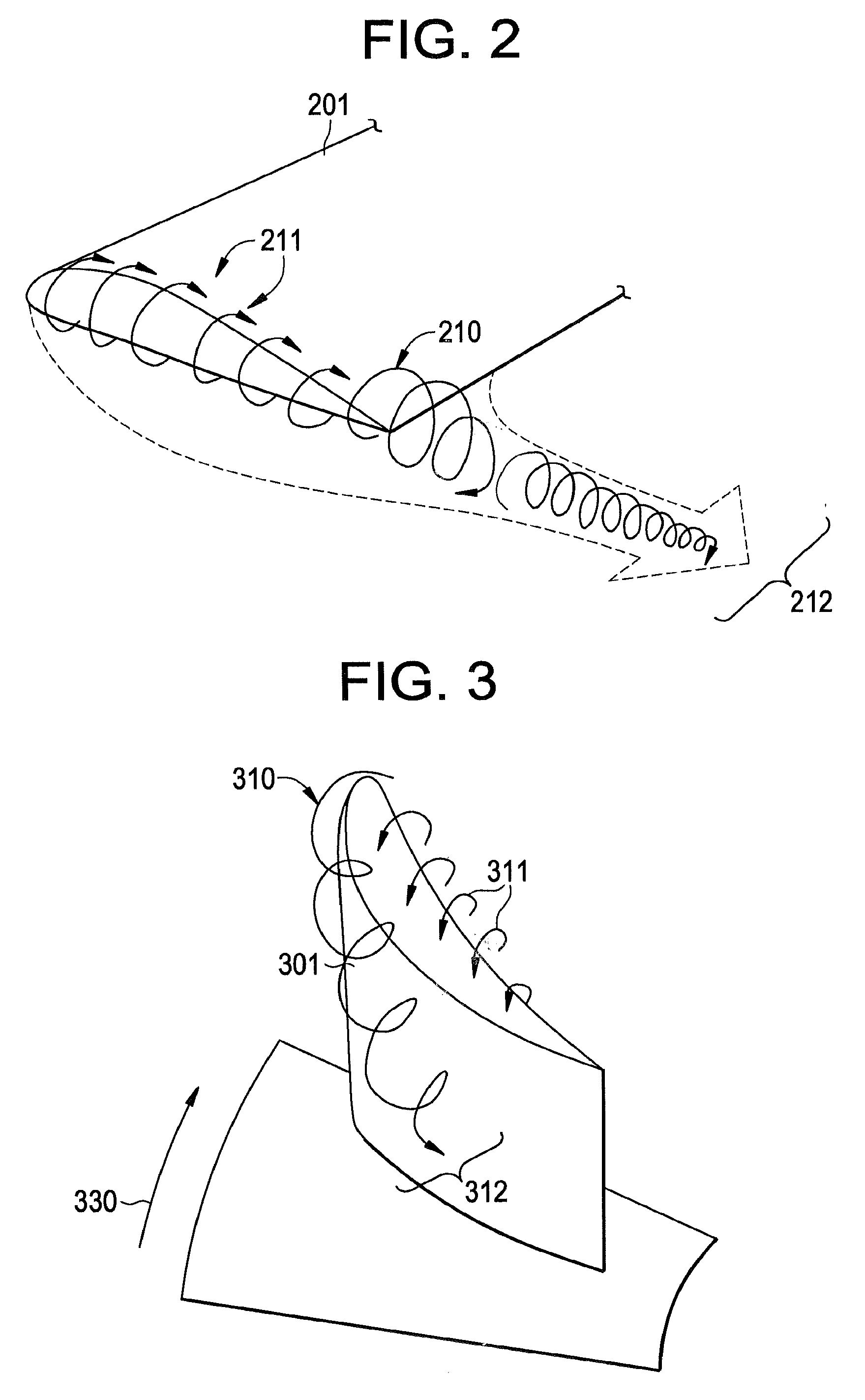
Generally, tip vortices and wakes shed by blades in aircraft engines, power generation equipment (e.g., wind and gas turbines), and their interactions with other systems utilizing airfoils are a source of aerodynamic loss, noise, and excitation phenomena.
For example, tip-vortices and wake from fan blades interact with downstream stators to give rise to fan noise, which is one of the main sources of aircraft engine noise.
The interaction noise in such designs becomes a technological hurdle for the design's success.
Furthermore, interaction event

Method used


Image

  • Reduction of Tip Vortex and Wake Interaction Effects in Energy and Propulsion Systems
  • Reduction of Tip Vortex and Wake Interaction Effects in Energy and Propulsion Systems
  • Reduction of Tip Vortex and Wake Interaction Effects in Energy and Propulsion Systems

Examples


Embodiment Construction

[0020]Detailed illustrative embodiments are disclosed herein. However, specific functional details disclosed herein are merely representative for purposes of describing example embodiments. Example embodiments may, however, be embodied in many alternate forms and should not be construed as limited to only the embodiments set forth herein.

[0021]Accordingly, while example embodiments are capable of various modifications and alternative forms, embodiments thereof are shown by way of example in the drawings and will herein be described in detail. It should be understood, however, that there is no intent to limit example embodiments to the particular forms disclosed, but to the contrary, example embodiments are to cover all modifications, equivalents, and alternatives falling within the scope of example embodiments.

[0022]As used herein, the singular forms “a”, “an” and “the” are intended to include the plural forms as well, unless the context clearly indicates otherwise. It will be furth...


PUM


Abstract

An airfoil includes a plasma actuation surface integrated onto the airfoil surface. On the airfoil, the plasma actuation surface is configured to provide high-frequency plasma actuation along the plasma actuation surface such that excitation of the vortex flow or shear flow mitigates the vortex flow or the shear flow associated with the airfoil.

Description

BACKGROUND OF THE INVENTION[0001]Embodiments of the invention generally relate to plasma actuation, and more particularly to tip-vortex mitigation and wake mitigation via plasma actuation for reduction of interaction events.[0002]Generally, tip vortices and wakes shed by blades in aircraft engines, power generation equipment (e.g., wind and gas turbines), and their interactions with other systems utilizing airfoils are a source of aerodynamic loss, noise, and excitation phenomena.[0003]For example, tip-vortices and wake from fan blades interact with downstream stators to give rise to fan noise, which is one of the main sources of aircraft engine noise. This may be exacerbated in fan designs such as un-ducted fans which feature two-prop fans within relatively close proximity. The interaction noise in such designs becomes a technological hurdle for the design's success. Furthermore, interaction events give rise to aerodynamic issues, for example in turbo-machinery, where unsteady impu...

Claims


Application Information

Patent Timeline
IPC IPC(8): B64C23/06
CPCB64C23/005Y02T50/164B64C23/065Y02T50/10
Inventor GUPTA, ANURAGSADDOUGHI, SEYED GHOLAMALI
Owner GENERAL ELECTRIC CO
Why Eureka
Try Eureka