Golf club grip and manufacturing method thereof

a golf club and grip technology, applied in the field of golf accessories, can solve the problems of golf club slipping out of golf club power not being transmitted through the hands of the golfer, and affecting the golfer in substantial ways

Inactive Publication Date: 2010-07-29
CHEN YUNG HSIANG +1
View PDF11 Cites 15 Cited by
  • Summary
  • Abstract
  • Description
  • Claims
  • Application Information

AI Technical Summary

Benefits of technology

[0014]A main object of the present invention is to provide a golf club grip which has at least two integrated portions with different natures to form a tapered tubular body for attaching to a holding end portion of a shaft of a golf club. Therefore, the golfer is able to tailor make the golf club grip depending on the personal preference and need by selecting the fabric textile, color, hardness and viscosity of each of the first and second members of the golf club grip.

Problems solved by technology

On the other hand, if the golfer grips his or her golf club too loose, the golf club may slip out of his or her hands through the golf swing.
Also, the power from the uncoiling body will fail to transmit to the golf club through the golfer's hands.
Therefore, the nature and surface condition of the grip can substantially affect the golfer to apply the appropriate grip pressure.
Some golf club grips provide anti-slip design on the grip surface for better frictional contact with the golfer's hands, it can substantially help to prevent slipping and provide constant grip pressure throughout the swing for the holding hand but may adversely affect the control and feeling of the controlling hand.
However, any excess grip pressure through the hand may also tense the arm and shoulder muscles and unexpectedly affect the golf swing.

Method used


Image

  • Golf club grip and manufacturing method thereof
  • Golf club grip and manufacturing method thereof
  • Golf club grip and manufacturing method thereof

Examples


Embodiment Construction

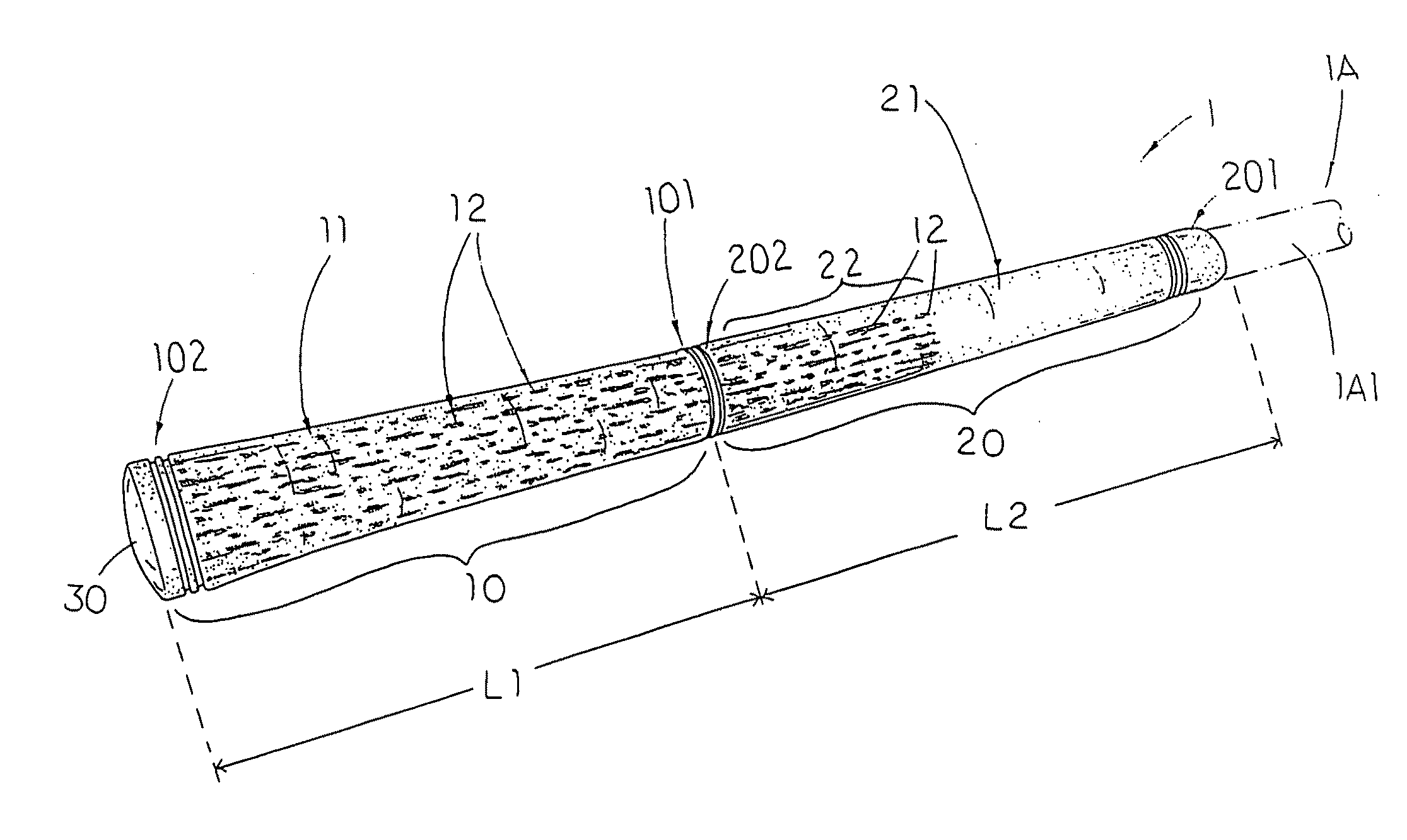
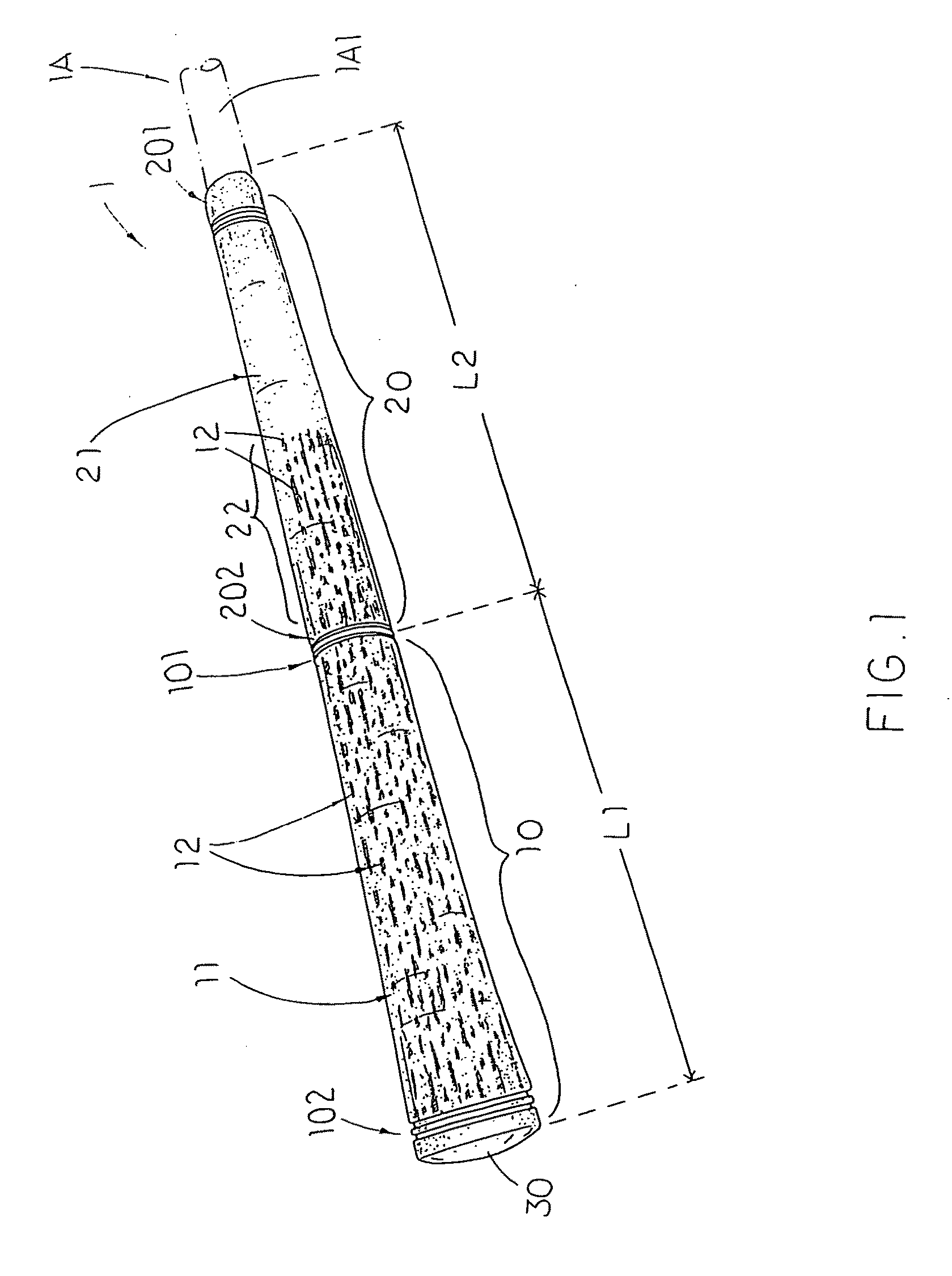
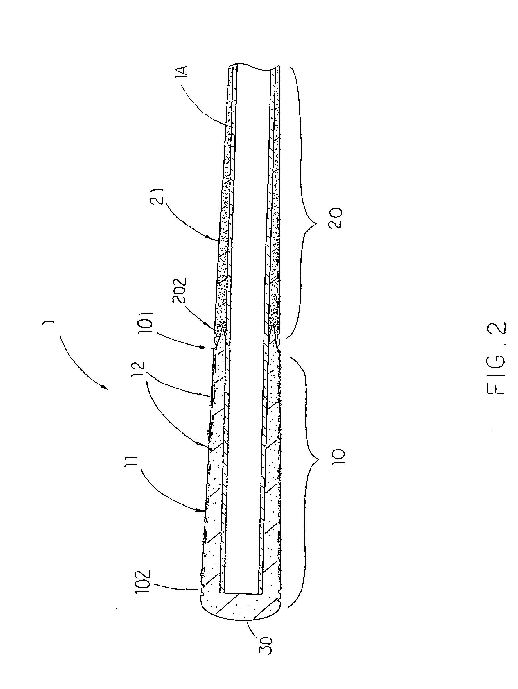
[0050]Referring to FIGS. 1 to 4 and 6 of the drawings, a golf club grip 1 for a golf club 1A according to a preferred embodiment of the present invention is illustrated, wherein the golf club grip 1 comprises a first member 20 and a second member 10.

[0051]The second member 20, which is rubber made tube, has a lower end 201, an upper end 202 and a gripping surface 21 defining between the upper end 202 and the lower end 201.

[0052]The first member 10, which is rubber made tube, has an upper end 102 and a lower end 101 coaxially integrated with the upper end 202 of the first member 20 to form an elongated integral tubular body for attaching to an upper end portion of the shaft of the golf club 1A, wherein the first member 10 has an outer circumferential surface 11 integrally extended from the gripping surface 21 of the second member 20. The first and second members 20, 10 have different natures to provide two different properties.

[0053]A shown in FIGS. 1 to 4, the first member 10 forms ...


PUM

PropertyMeasurementUnit
weightaaaaaaaaaa
weightaaaaaaaaaa
weightaaaaaaaaaa

Abstract

A method of manufacturing a golf club grip includes the step of: (a) forming a first grip member in a first mold having a first predetermined mold pattern by vulcanizing a predetermined of non-vulcanized rubber material in the first predetermined mold, wherein the first grip member has a plurality of first pattern channels formed thereon corresponding with the first predetermined mold pattern; (b) disposing the first grip member in a second mold having a second predetermined mold pattern; and (c) forming a second grip member in the second mold by vulcanizing a predetermined amount of non-vulcanized rubber material in the second mold, wherein the second grip member has a plurality of second pattern channels formed thereon corresponding to the second predetermined mold pattern, wherein the first grip member and the second grip member are integrated in an edge-to-edge manner without intermixing of color and material.

Description

CROSS REFERENCE OF RELATED APPLICATION[0001]This is a Continuation-In-Part of a non-provisional application having an application Ser. No. 11 / 982,097 and a filing date of Oct. 31, 2007, which is also a Continuation-In-Part of a non-provisional application having an application Ser. No. 11 / 604,129 and a filing date of Nov. 22, 2006, which is a Continuation-In-Part of a non-provisional application having a application Ser. No. 11 / 192,775 and a filing date of Jul. 29, 2005, and is a Continuation-In-Part of a non-provisional application having an application Ser. No. 10 / 771,710, a filing date of Feb. 3, 2004, and a U.S. Pat. No. 7,008,582, which is a Continuation-In-Part of a non-provisional application having an application Ser. No. 29 / 196,500, a filing date of Dec. 29, 2003, and a U.S. Pat. No. D,502,750.BACKGROUND OF THE PRESENT INVENTION[0002]1. Field of Invention[0003]The preset invention relates to a golf accessory, and more particularly to a golf club grip having at least two int...

Claims


Application Information

Patent Timeline
Patent Type & Authority Applications(United States)
IPC IPC(8): A63B53/14B29C39/12
CPCA63B53/14A63B2209/00A63B2071/0694A63B69/3632A63B60/14A63B60/00
Inventor CHEN, YUNG HSIANGCHEN, JASON
Owner CHEN YUNG HSIANG
Why Eureka
Try Eureka