

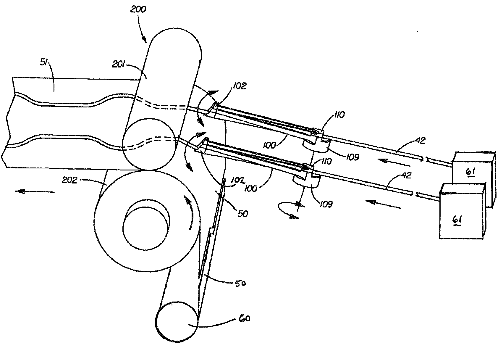
System and Method for High-Speed Continuous Application of a Strip Material to a Moving Sheet-Like Substrate Material at Laterally Shifting Locations
- Summary
- Abstract
- Description
- Claims
- Application Information
AI Technical Summary
Problems solved by technology
Method used
Image

Examples
Embodiment Construction
[0029]The dimensions and values disclosed herein are not to be understood as being strictly limited to the exact numerical values recited. Instead, unless otherwise specified, each such dimension is intended to mean both the recited value and a functionally equivalent range surrounding that value. For example, a dimension disclosed as “40 mm” is intended to mean “about 40 mm.”
DEFINITIONS
[0030]For purposes of this description, the following terms have the meanings set forth below:
[0031]Connected: With respect to a relationship between two mechanical components, unless otherwise specified, “connected” means that the components are directly physically connected to each other, or indirectly physically connected to each other through intermediate components. Unless otherwise specified, “connected” is not meant to imply or be limited to a connection that causes the components to become immovably fixed with respect to each other.
[0032]Continuous supply: With respect to a supply of sheet- o...
PUM
| Property | Measurement | Unit |
|---|---|---|
| Speed | aaaaa | aaaaa |
| Elasticity | aaaaa | aaaaa |
| Velocity | aaaaa | aaaaa |
Abstract
Description
Claims
Application Information