
Brake wear measurement system and method

Active Publication Date: 2010-08-19
THE BF GOODRICH CO
View PDF8 Cites 15 Cited by
  • Summary
  • Abstract
  • Description
  • Claims
  • Application Information

AI Technical Summary

Benefits of technology

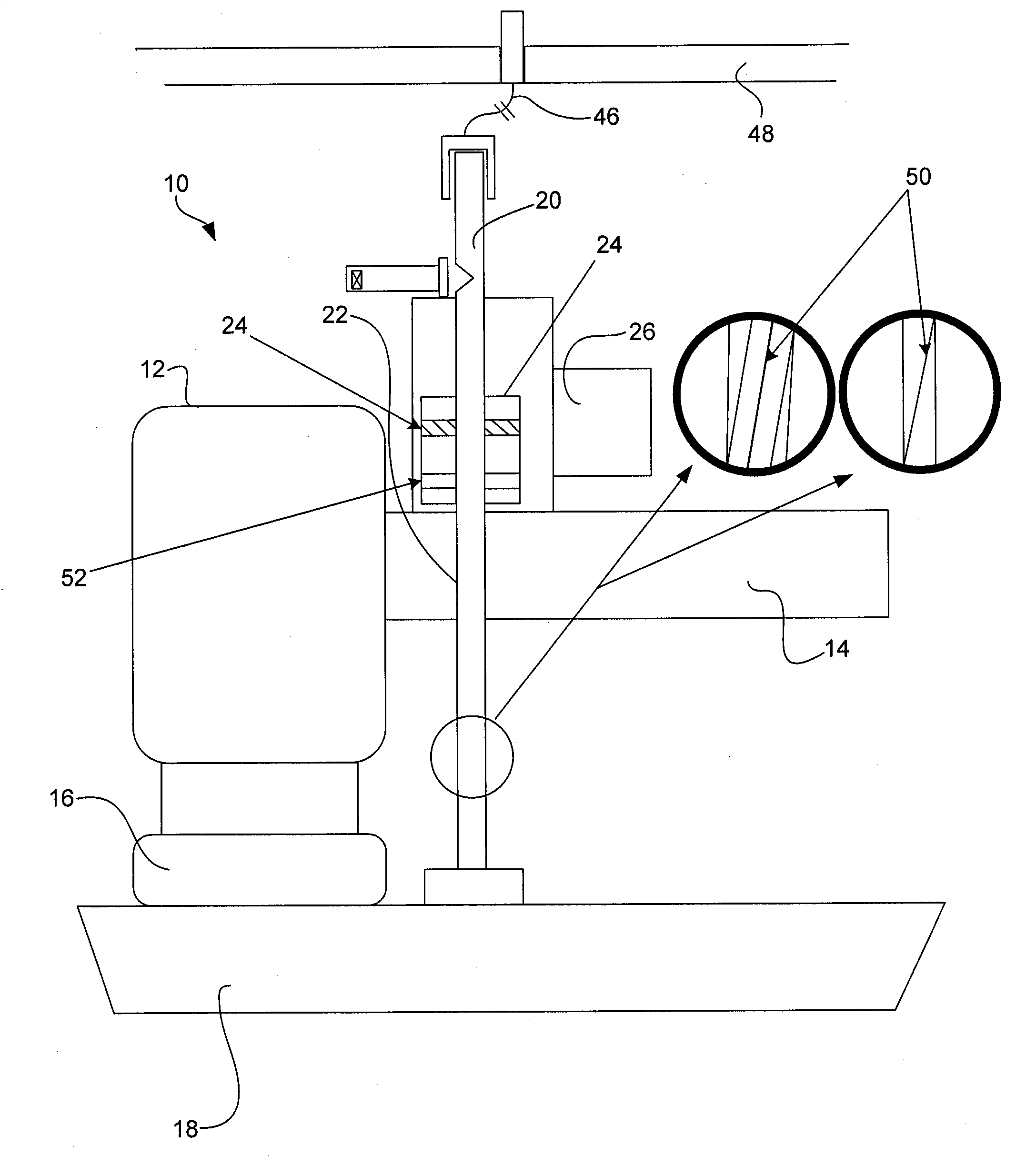
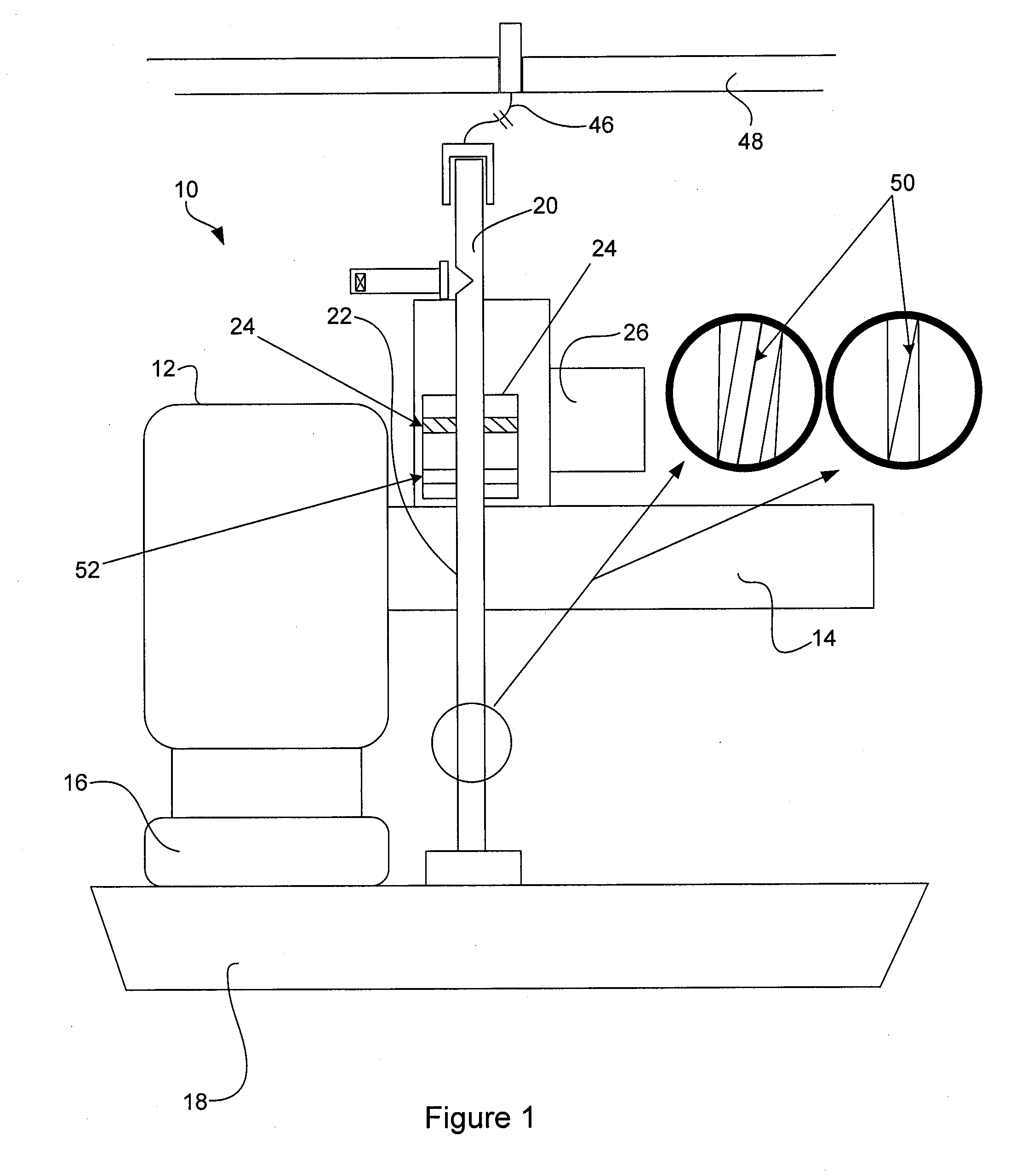
[0005]The displacement sensor may be fitted with a scraper that engages the measurement mechanism and removes contaminants and debris from a measured surface of the measurement mechanism. The brake wear measurement system may further comprise a mechanical calibration mechanism that interfaces with the measurement mechanism providing for single point calibration. In an embodiment, the displacement sensor is fitted with a connector, enabling communication of the displacement sensor to a brake control system (or other aircraft system). The measurement mechanism may further comprise a visual

Problems solved by technology

However, the wear pin is typically installed as part of the brake assembly inside the aircraft wheel making visual inspection difficult.
Such installation and inspection is also potentially difficult because of the harsh environment created by the aircraft braking system and the closed system created when the brake assembly is installed inside the wheel.

Method used


Image

  • Brake wear measurement system and method
  • Brake wear measurement system and method
  • Brake wear measurement system and method

Examples


Embodiment Construction

[0018]The detailed description of exemplary embodiments herein makes reference to the accompanying drawings, which show exemplary embodiments by way of illustration and its best mode, and not of limitation. While these exemplary embodiments are described in sufficient detail to enable those skilled in the art to practice the invention, it should be understood that other embodiments may be realized and that logical, chemical and mechanical changes may be made without departing from the spirit and scope of the invention. For example, the steps recited in any of the method or process descriptions may be executed in any order and are not necessarily limited to the order presented. Moreover, many of the functions or steps may be outsourced to or performed by one or more third parties. Furthermore, any reference to singular includes plural embodiments, and any reference to more than one component or step may include a singular embodiment or step. Also, any reference to attached, fixed, co...


PUM


Abstract

A brake measurement system comprising a measurement mechanism for measuring brake wear operatively coupled to a moveable member of a brake assembly is provided. The system further includes a displacement sensor and a visual indicator. The displacement sensor is operatively coupled to the measurement mechanism, wherein movement of the moveable member is converted by the measurement mechanism into a displacement sensed by the displacement sensor. The visual indicator is operatively connected to the measurement mechanism, wherein the visual indicator displays the movement of the moveable member and consequently the wear of the brake stack at a point on the exterior of an aircraft brake housing for inspection.

Description

CROSS-REFERENCE TO RELATED APPLICATIONS[0001]This application is a continuation-in-part of U.S. application Ser. No. 12 / 372,069, filed on Feb. 17, 2009, and entitled “BRAKE WEAR MEASUREMENT SYSTEM”, the content of which is hereby incorporated by reference in its entirety.FIELD OF INVENTION[0002]This invention generally relates to braking systems, and more particularly, to electronic brake control systems for aircraft.BACKGROUND OF THE INVENTION[0003]Prior art aircraft brake systems often employ wear pin indicators to measure overall wear of the brake disk stack. Brake wear is indicated by the length of the pin relative to a reference plate. This system generally requires a visual inspection of the pin to determine wear. However, the wear pin is typically installed as part of the brake assembly inside the aircraft wheel making visual inspection difficult. Such installation and inspection is also potentially difficult because of the harsh environment created by the aircraft braking sy...

Claims


Application Information

Patent Timeline
IPC IPC(8): F16D55/36G01P21/00
CPCF16D2066/003F16D66/026
Inventor CAHILL, ERIC DANIEL
Owner THE BF GOODRICH CO
Learn More