
Eureka
For R&D, Eureka makes reading and utilizing patents & technical documents easy.
Eureka AIR
Designed for self-driven R&D workflows. Generate viable solutions, solve complex R&D challenges, empower your innovation with AI.

Eureka Materials
Designed for material experts only. Revolutionize your material R&D, from search, analyze, to developing new materials.

TechResearch
Generate reliable direction feasibility study reports for your R&D in just a few steps.

TechSeek
Discover and master advanced knowledge NOW. Basics, ideas, possibilities, all at once.

TechMind
As an expert in R&D Theories, TechMind can generates customized viable solutions instantly.

TechRisk
Analyze your overall solution with one click, know your potential R&D risks in advance.

TechMonitor
Get weekly tech updates, stay abreast of the latest tech innovations and key insights.
Release Handle Assembly Having Inertial Blocking Member with Blocking Member Retainer
- Summary
- Abstract
- Description
- Claims
- Application Information
AI Technical Summary
Problems solved by technology
Method used
Image

Examples
first embodiment
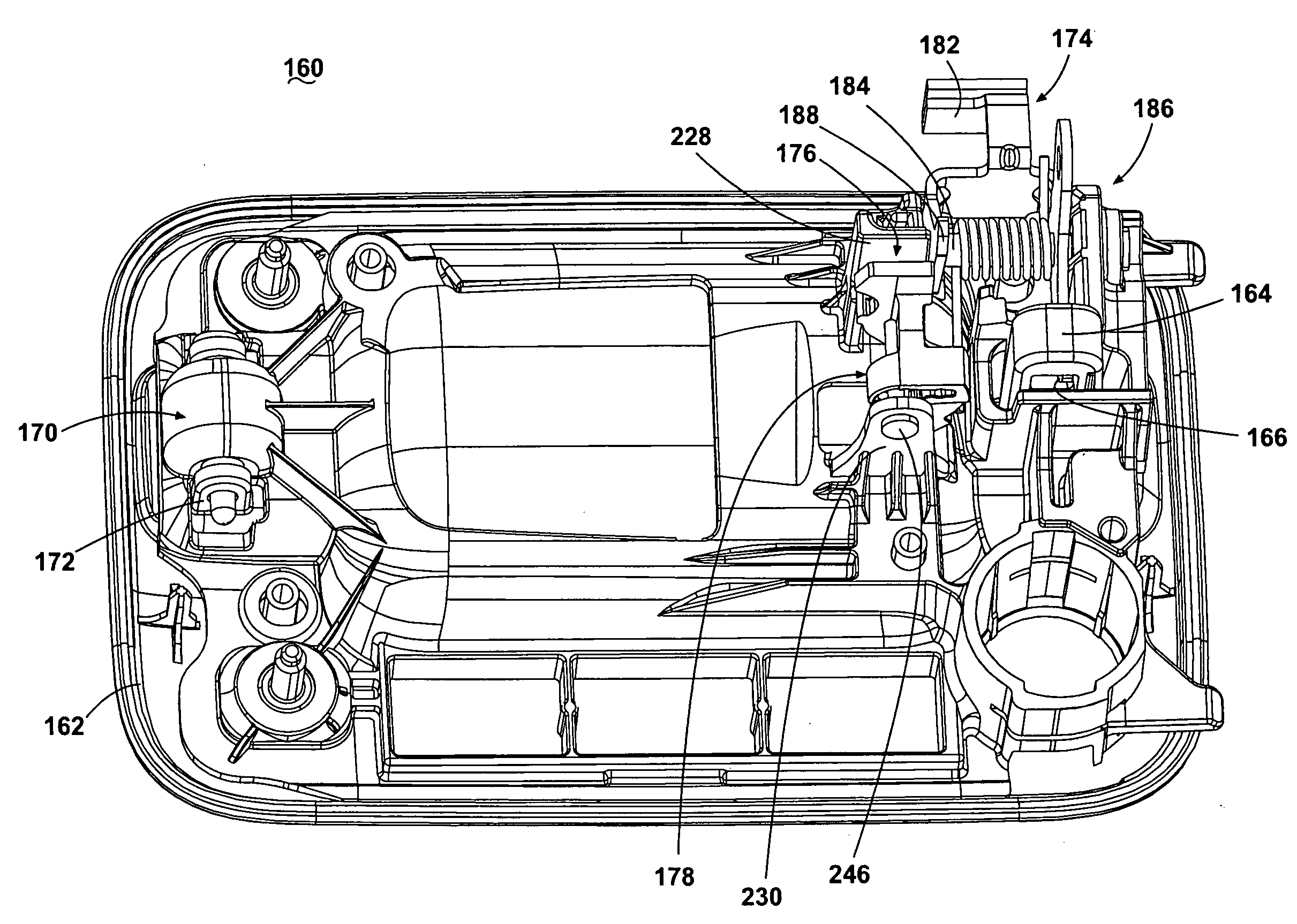
[0054]Referring now to FIGS. 4 and 5, an inertial blocking member subassembly 176, incorporating the hidden CG features described above, is illustrated comprising part of a release handle assembly 160. The release handle assembly 160 comprises an escutcheon 162 and a door handle grip (not shown) for operating a bell crank assembly 174. The door handle grip comprises a latch arm 164 at a first end and a pivot arm (not shown) rotatably received in a pivot arm housing 170 through a pivot pin 172. Pulling on the door handle grip can pivot the door handle grip about the pivot pin 172, moving the latch arm 164 outwardly of the release handle assembly 160. Alternatively, the release handle assembly 160 can be comprised of other handle / latch assemblies, such as a paddle-type or twist-type latch assembly.
[0055]The bell crank assembly 174 comprises a bell crank transitioning to a crank finger 166 extending radially away from the support pin 184 at a first, generally following end, which slida...
third embodiment
[0074]The third embodiment comprises an inertial blocking member 250, illustrated in FIGS. 17A-C, which is rotatably mounted between a lower support feature 284 and an upper support feature 286 by the pin 246 (FIG. 18A). The inertial blocking member 250 is urged toward the at-rest position and upwardly toward the upper support feature 286 by a suitable biasing member, such as a helical spring (not shown), which can be disposed concentrically with the pin 246. Extending inwardly from the release handle assembly framework 186 is an elongated, somewhat cantilevered frame projection 308 terminating in an orthogonally-disposed planar stop surface 310.
[0075]Referring to FIGS. 17A-C, the inertial blocking member 250 comprises a hidden CG counterweight portion 252 and an interference portion 254. The hidden CG counterweight portion 252 comprises a bottom wall 258. The interference portion 254 comprises a top wall 256. The top wall 256 is joined with the bottom wall 258 by a side wall 260.
[0...
fourth embodiment
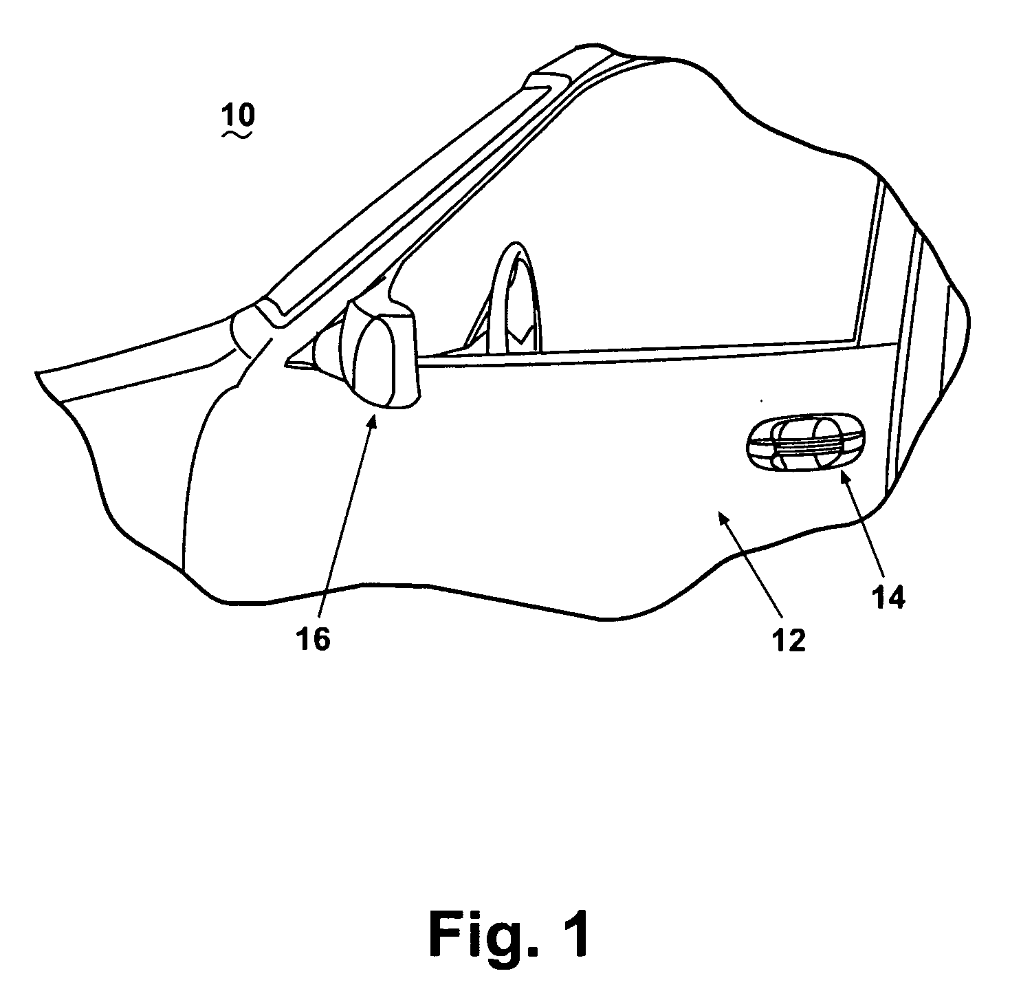
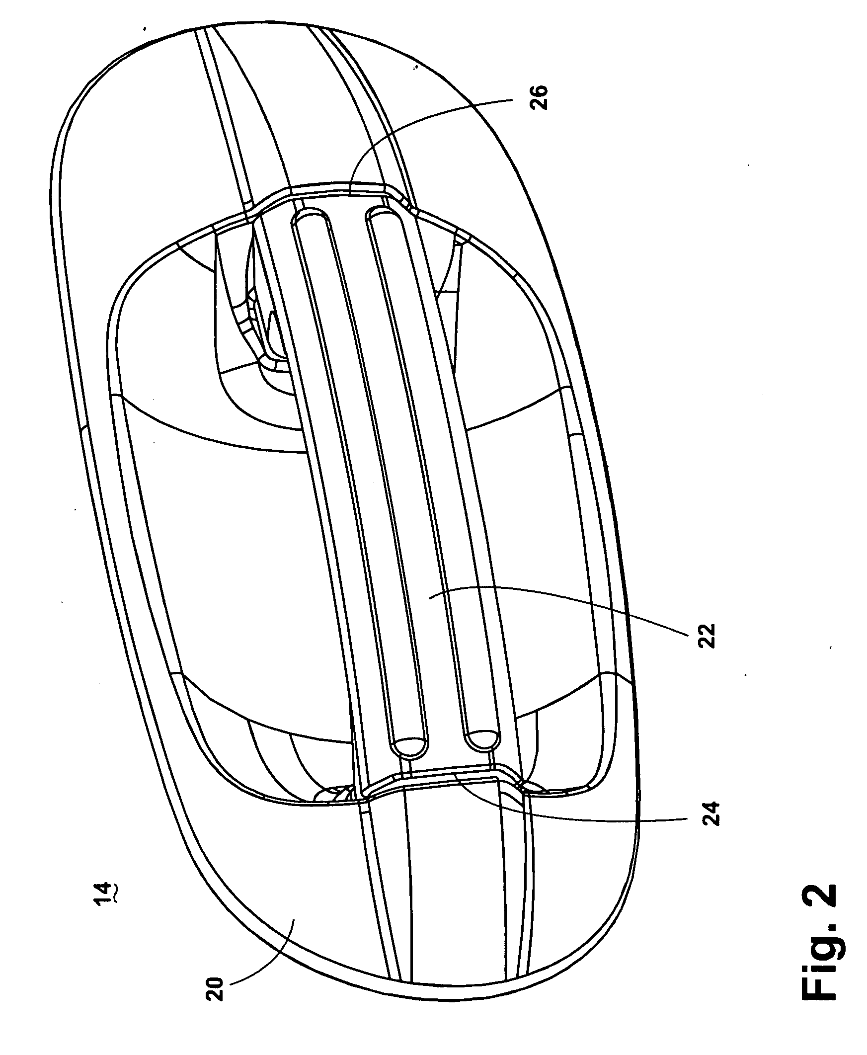
[0085]FIGS. 23-28 illustrate the invention. The door handle grip 22 comprises a support end 24 and an opposed latch end 26. Extending somewhat orthogonally away from the door handle grip 22 at the support end 24, as illustrated in FIGS. 23 and 24, is an elongated support arm 28 having a generally constant cross-section, illustrated herein as generally rectilinear. Similarly, extending orthogonally away from the door handle grip 22 at the latch end 26 is a latch arm 30 having a generally rectilinear cross-section.
[0086]Each arm 28, 30 terminates proximate its inward end in a vertically disposed rectilinear slot 35, 37, respectively. The support arm 28 and the latch arm 30 are slidably received within complementary tube-like handle sleeves 56, 54, respectively, rigidly coupled with the escutcheon 20. Pulling on the door handle grip 22 from the exterior side of the vehicle 10 can slidably translate the arms 28, 30 toward the exterior of the door assembly 12.
[0087]A bell crank actuator ...
PUM
 Abstract
Description
Claims
Application Information
 - R&D Engineer
- R&D Manager
- IP Professional
- Industry Leading Data Capabilities
- Powerful AI technology
- Patent DNA Extraction
Browse by: Latest US Patents, China's latest patents, Technical Efficacy Thesaurus, Application Domain, Technology Topic, Popular Technical Reports.
© 2024 PatSnap. All rights reserved.Legal|Privacy policy|Modern Slavery Act Transparency Statement|Sitemap|About US| Contact US: help@patsnap.com