Chiropractic posture correction tool

a posture correction and tool technology, applied in the field of chiropractic health care, can solve the problems of limited use, lack of postural correction, and inability to assist the chiropractor, and achieve the effect of maximal neurological correction and “pre-stress”

Inactive Publication Date: 2010-08-19
POSTURE CORRECTION TOOLS
View PDF27 Cites 19 Cited by
  • Summary
  • Abstract
  • Description
  • Claims
  • Application Information

AI Technical Summary

Benefits of technology

[0019]Finally, the table of the present invention utilizes polyurethane pads that will not lose the integrity of their density as compared to upholstered foam pads. The densities of the pads have been designed to maximize the “pre-stress” needed for optimal mechano-reception and thus maximal neurological correction. Therefore, the practitioner needs to apply a force to the spine to take up slack in the polyurethane while following through to complete a drop.

Problems solved by technology

In the experience of this inventor, chiropractic tables of the prior art lack certain functionalities that could assist the chiropractor in the application of his or her treatment of the patient.
For example, while such tables may include drop sections for assisting the chiropractor during application of the above-mentioned manipulative joint thrust, which is also known as a “drop adjustment,” they are very limited in their use.
1. Flying drops (thoracic and lumbar) in the thoracic and lumbar sections. “Flying drops” are defined as the thoracic and lumbar sections of the table of the present invention which are able to be raised and angled and cocked and dropped in any position. These “flying drops” allow the chiropractor to set up a patient in a specific posture and perform a drop adjustment without adding any incorrect postures. In other words, conventional drops find chiropractors unable to perform a drop without adding an incorrect posture to the patient's spine. In the past, attempts were made to compensate for the lack of “flying drops” by using foam wedges. These wedges, however, rarely allowed for an exacting postural set-up prior to a drop being administered. Therefore, chiropractors were often frustrated with the lack of postural correction results because they were often adding improper postures.
2. Pelvic elevation “flying drop” in the pelvic section. The pelvic section of the table can be raised, cocked, and dropped at any height. Here again, this “flying drop” allows the chiropractor to set up a patient in a specific posture and perform a drop adjustment without adding any incorrect postures. Conventional drops find chiropractors unable to perform a drop without adding an incorrect posture to the patient's spine and attempts were made to compensate for the lack of “flying drops” by using foam wedges. These wedges, however, rarely allowed for an exacting postural set-up prior to a drop being administered. As a result, chiropractors were often frustrated with the lack of postural correction results because they were often adding improper postures.
3. The cervical instrument adjusting fulcrum is a unique feature elevates and rotates in order to provide exact positioning for critical cervical instrument adjusting.
4. A head piece that lowers up to three inches (3″) below table horizontal while remaining fully functional in thirty degree)(30°) flekion and extension drop. This unique feature provides chiropractors the ability to have the table compensate for anterior or lateral head translation without adding unwanted postures when performing cervical drop work. Additionally, whether the head piece is raised or lowered, it maintains full functionality in thirty degree)(30°) flexion and extension drops.
5. The use of polyurethane pads, for the first time, provide a predictable rebound during the patient adjustment. In addition, is the polyurethane pad allows, for the first time, for a “pre-stress” to be used just prior to following through with the drop in an adjustment. The polyurethane pads have also allowed flexibility of a futuristic design that includes beveled edges and more of a human form outline for easier on- and off-patient access, as well as easier approach to the table by the chiropractor. Up to this point, chiropractic tables had traditionally been covered with a foam product that was limited in all that was described above.
6. This table was also designed for ease of mobility. It has lift rods at the head and foot of the table. It has wheels that are easily inserted or removed. Aside from portable chiropractic tables, the heavier permanent tables have not been designed with mobility in mind.
7. The table of the present invention was engineered with safety in mind. The majority of conventional “pinch points” have been eliminated.

Method used


Image

  • Chiropractic posture correction tool
  • Chiropractic posture correction tool
  • Chiropractic posture correction tool

Examples


Embodiment Construction

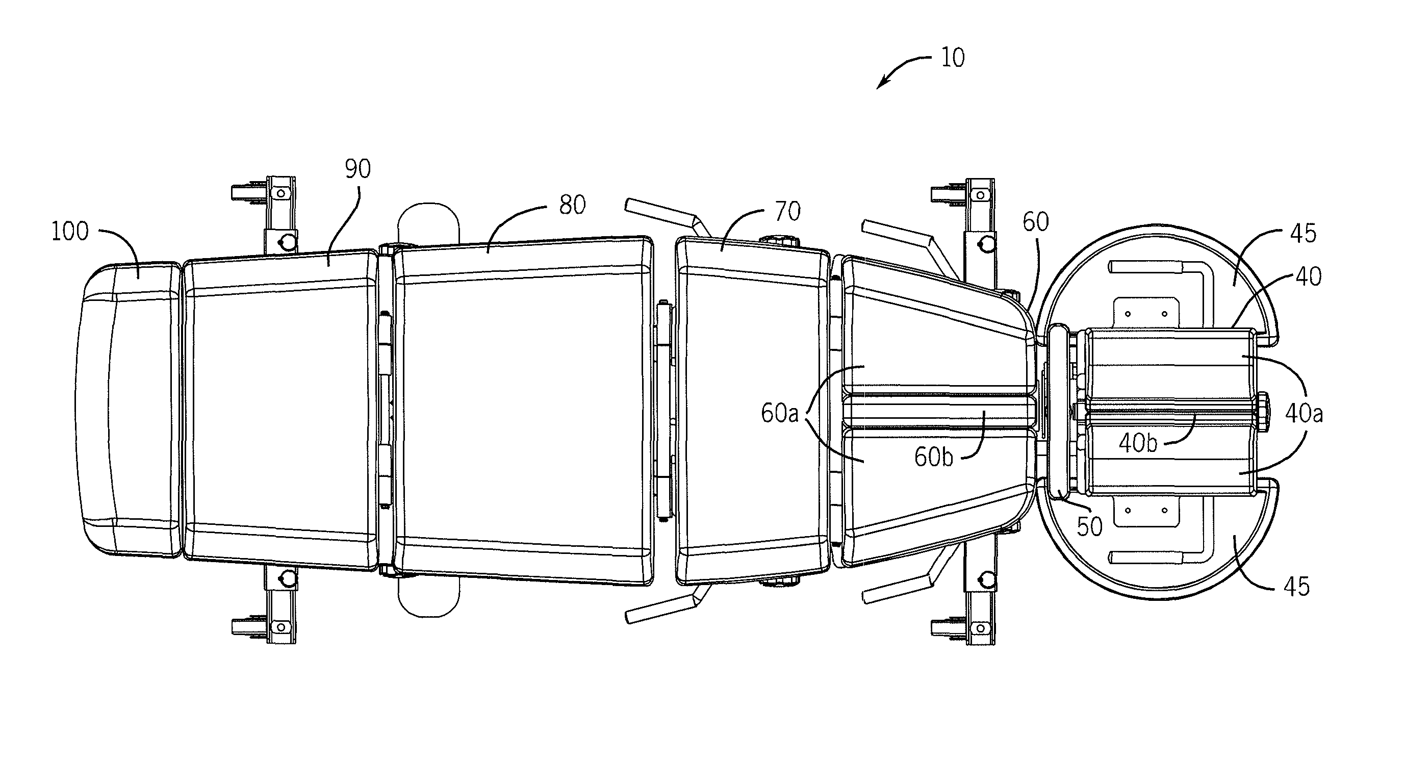
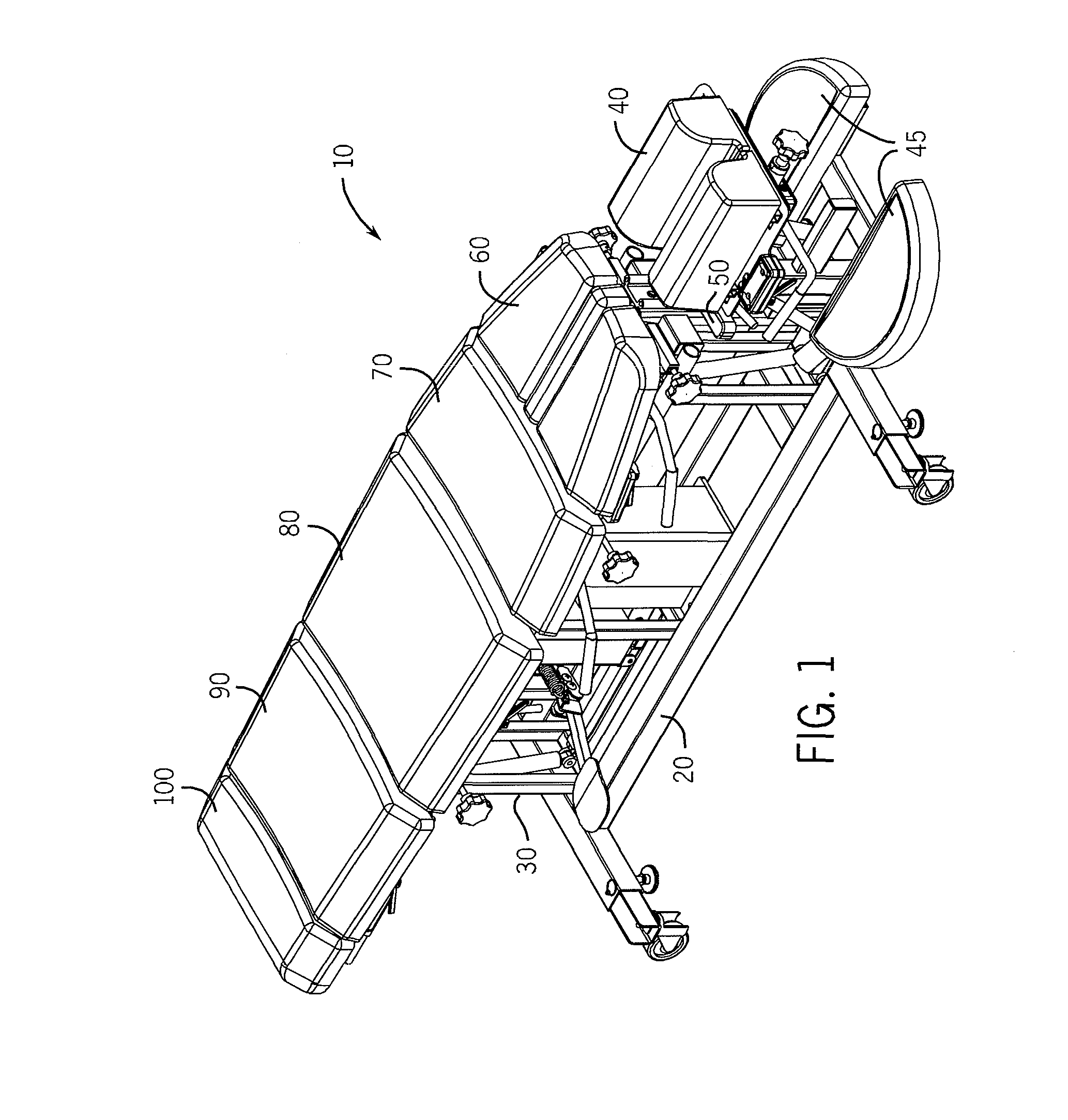
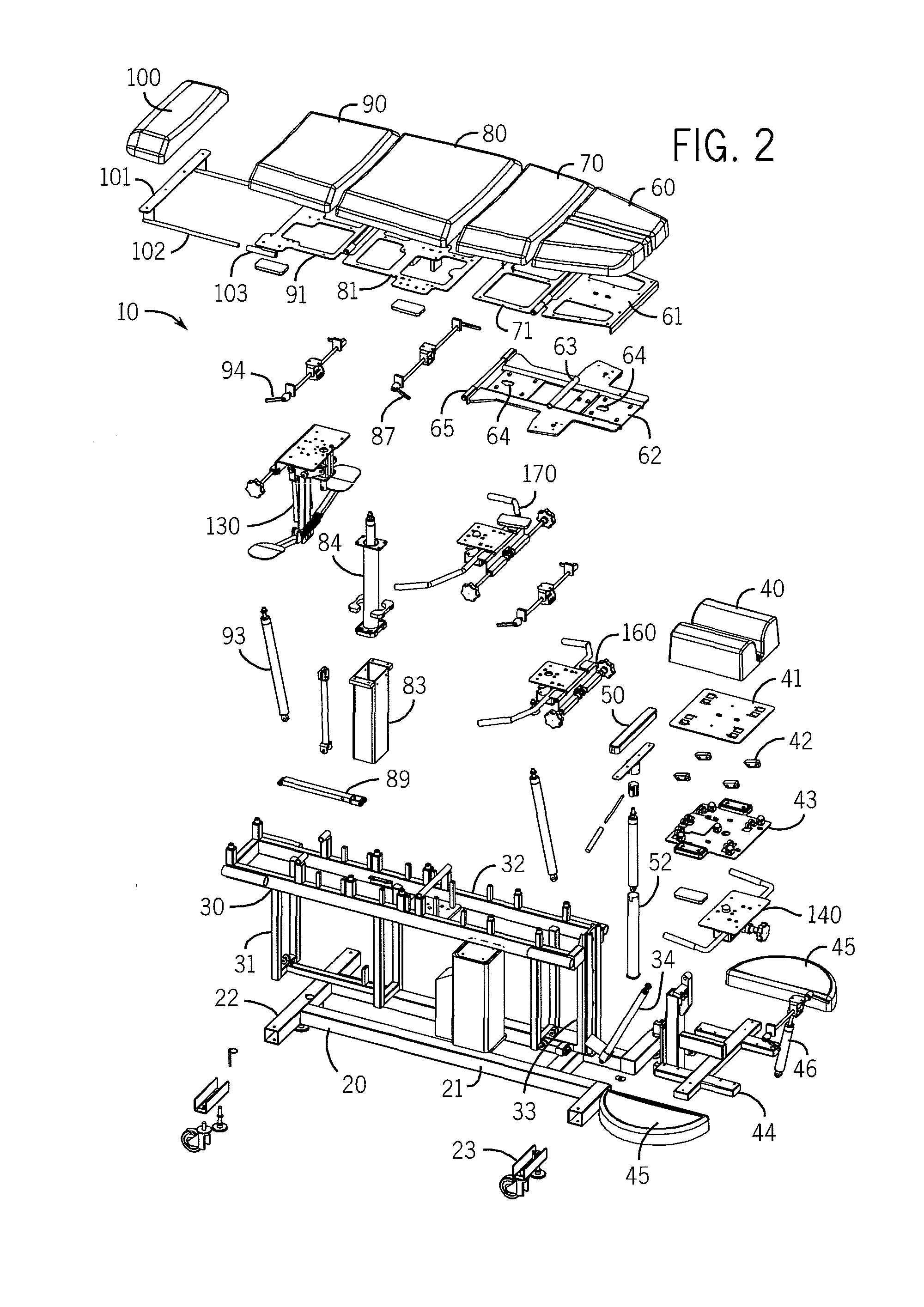
[0050]Referring now to the drawings in detail, wherein like numbered elements refer to like elements throughout, FIGS. 1 through 4 illustrate a representative structure, generally identified 10, which is a preferred embodiment of a posture correction tool table that is constructed in accordance with the present invention. Generally speaking, the table 10 comprises a plurality of pads that are mounted onto a superstructure. It is this plurality of pads that support the patient during chiropractic treatment. More specifically, and moving from that forward-most point of the table 10 where the patient's head (not shown) would rest, it will be seen that the pads comprise a head pad 40, a cervical pad 50, a composite thoracic pad 60, a lumbar pad 70, a pelvic pad 80, a leg pad 90, and a foot pad 100. Additionally, two semi-circular shaped arm pads 45 are located and mounted to either side of the head pad 40. This allows the patient, who is supported in the prone position by the table 10, ...


PUM


Abstract

The claimed invention provides an improved posture correction tool in the form of a table to be used by chiropractic practitioners to treat mechanical disorders of the spine and musculoskeletal system. The improved posture correction tool provides a plurality of pads to support the various major areas of the body and has built in drop capability and adjustment capability for the pelvic pad, the lumbar pad, the thoracic pad and the head and cervical area. The claimed invention also has a novel cervical support.

Description

[0001]This application claims the priority and benefit of U.S. Provisional Patent App. Ser. No. 60 / 973,798 filed Sep. 20, 2007.FIELD OF THE INVENTION[0002]The present invention relates generally to chiropractic health care and to devices that are used in the area of chiropractic treatment. More specifically, the present invention relates to an improved posture correction tool in the form of a novel table that is used by chiropractic practitioners to treat mechanical disorders of the spine and musculoskeletal system.BACKGROUND OF THE INVENTION[0003]Chiropractic health care is well known. Chiropractic health care focuses on disorders of the musculoskeletal system and its related nervous system, and the effects that such disorders have on a patient's general health and well-being. Doctors of Chiropractic, alternatively referred to as “chiropractors” or “chiropractic physicians,” practice a drug-free, hands-on approach to health care that includes patient examination, diagnosis and trea...

Claims


Application Information

Patent Timeline
Patent Type & Authority Applications(United States)
IPC IPC(8): A61F5/00
CPCA61G13/009A61G13/08A61G13/12A61G13/121A61G13/122A61G2200/325A61G13/1235A61G13/1245A61G13/125A61G13/1255A61G13/123
Inventor RADERMACHER, MARK
Owner POSTURE CORRECTION TOOLS
Why Eureka
Try Eureka