
Stovetop grilling device

a grilling device and stovetop technology, applied in the field of stovetop grilling devices, can solve the problems of inability to experience cooking, inability to cook indoors, and inability to use indoor grilling, etc., and achieve the effect of increasing the width spacing

Inactive Publication Date: 2010-08-26
COUTTS STEPHEN
View PDF20 Cites 34 Cited by
  • Summary
  • Abstract
  • Description
  • Claims
  • Application Information

AI Technical Summary

Benefits of technology

"The present invention is a stovetop grilling device that solves the problems of previous inventions. It has a catch tray and a grilling surface with V-shaped members that provide a desired feature. The device has a uniform distance between the first and second members, and a drip reservoir to catch the drippings from the food. The grilling surface is placed on a stovetop burner and food is placed on the grilling surface and the burner is activated, the heat will follow an angled path upward to the grilling surface and downward to the catch tray. The grilling surface is pivoted at a hinge or has a removable catch tray. The device also includes a drip reservoir with a grease-trapping liquid, a stabilizing brace, a cover, and a vent. The cover can enclose the grilling surface and has a handle or a central handle. The invention solves the problems of previous inventions and provides a better grilling experience."

Problems solved by technology

Unfortunately for city dwellers, this experience is often denied them by the lack of suitable outdoor facilities.
Cooking over wood fires or even over a gas grill is too messy and dangerous to be done indoors.
The danger of open flames, spilled cooking grease, smoke and related conditions make indoor grill cooking impractical.

Method used


Image

  • Stovetop grilling device
  • Stovetop grilling device
  • Stovetop grilling device

Examples


Embodiment Construction

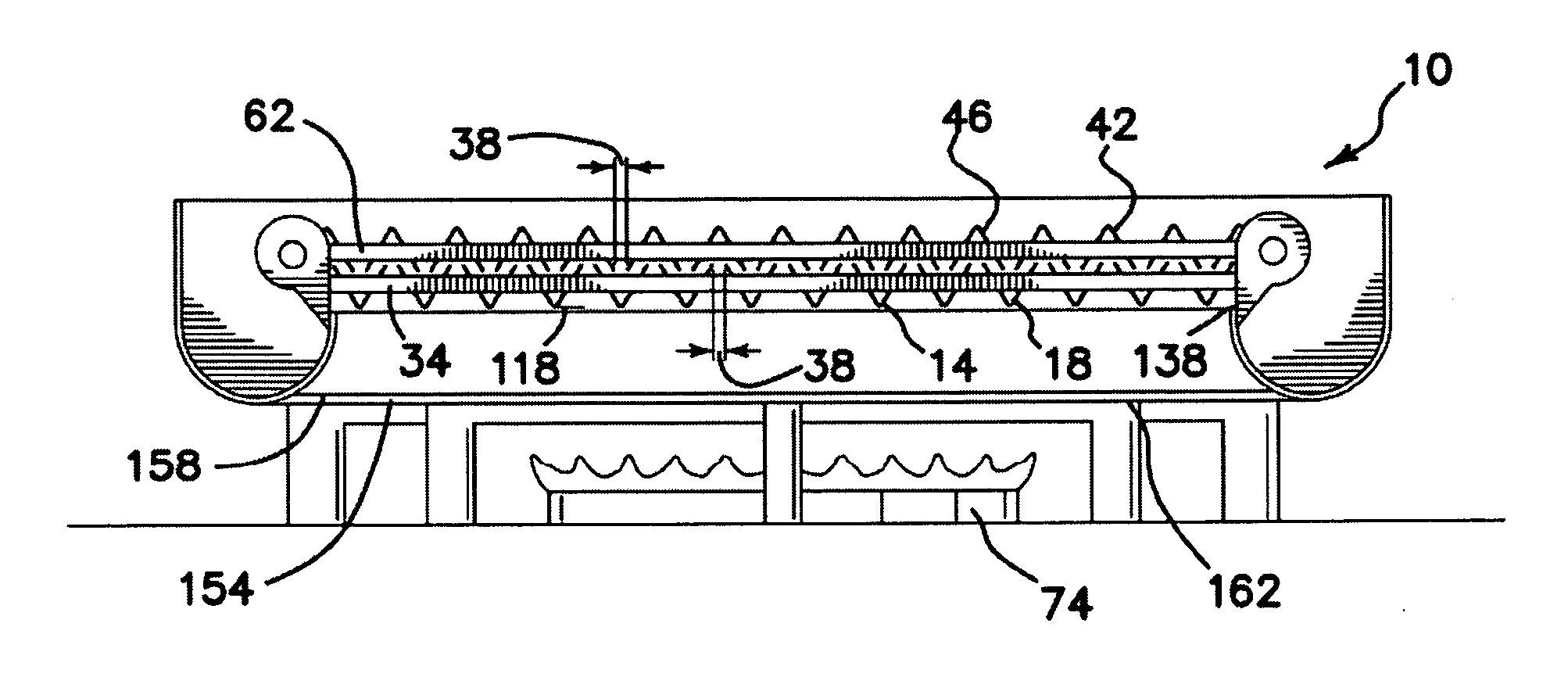
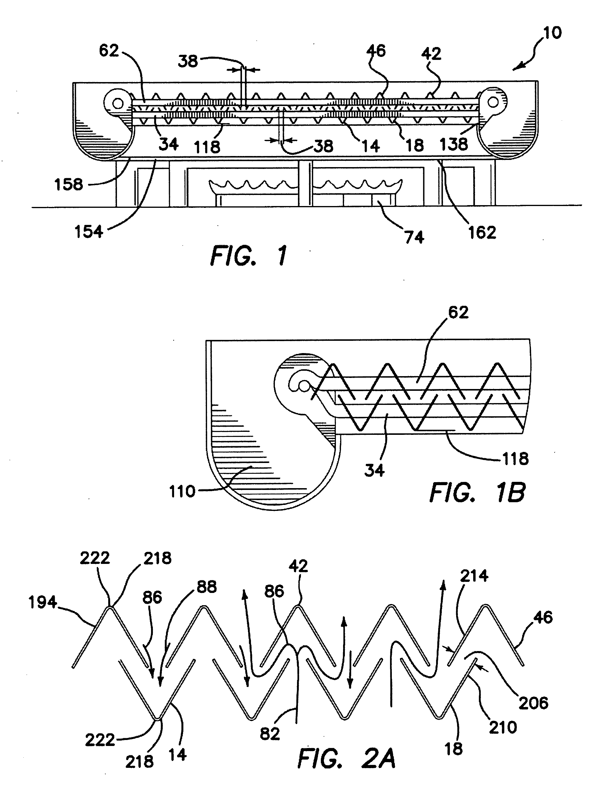
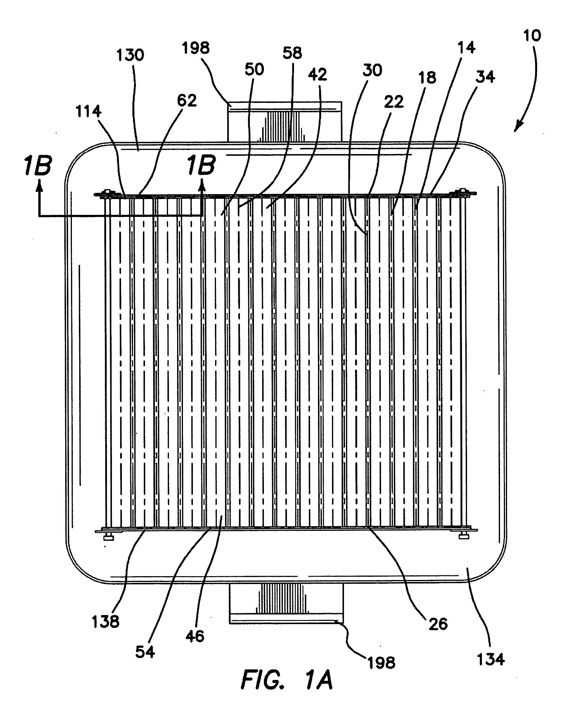
[0082](1) FIGS. 1-6 illustrate a stovetop grilling device 10 providing the desired features that may be constructed from the following components. A catch tray 14 is provided. The catch tray 14 has a plurality of downward pointing V-shaped first members 18. Each of the first members 18 has a first end 22, a second end 26 and parallel side edges 30. The first members 18 are attached at the first 22 and second 26 ends to a first supporting frame 34 and have the side edges 30 spaced from one another by a first distance 38. A grilling surface 42 is provided. The grilling surface 42 has a plurality of upward pointing V-shaped second members 46. Each of the second members 46 has a proximate end 50, a distal end 54 and parallel side edges 58. The second members 46 are attached at the proximate 50 and distal 54 ends to a second supporting frame 62 and have the side edges 58 spaced from one another by the first distance 38.

[0083]The second supporting frame 62, as illustrated in FIG. 2, is lo...


PUM


Abstract

A stovetop grilling device includes a catch tray that has a plurality of downward pointing V-shaped first members attached to a first frame and having parallel side edges spaced from one another by a first distance. A grilling surface has a plurality of upward pointing V-shaped second members attached to a second frame and having parallel side edges spaced from one another by the first distance. The second frame is located over the first frame with a mid-point between the parallel side edges of each of the first members centrally located between and below the parallel side edges of two adjacent second members and a mid-point between the parallel side edges of each of the second members centrally located between and above the parallel side edges of two adjacent first members. Heat follows an angled path upward to the grilling surface and food drippings flow downward to the catch tray.

Description

FIELD OF INVENTION[0001]This invention relates to the field of cooking equipment, and more specifically to a stovetop grilling device designed to provide indoor barbeque cooking.BACKGROUND OF THE INVENTION[0002]There has always been a tradition of outdoor cooking and barbequing in the United States. Many Americans are fans of the wood and smoke flavoring of meat and fish cooked on an outdoor grill, often over a wood fire. Unfortunately for city dwellers, this experience is often denied them by the lack of suitable outdoor facilities. Cooking over wood fires or even over a gas grill is too messy and dangerous to be done indoors. The danger of open flames, spilled cooking grease, smoke and related conditions make indoor grill cooking impractical. The present invention provides a solution that allows the urban dweller to enjoy the outdoor grilling experience in the comfort of his or her kitchen without the mess and danger associated with traditional outdoor grill cooking.[0003]U.S. Pat...

Claims


Application Information

Patent Timeline
Patent Type & Authority Applications(United States)
IPC IPC(8): A47J37/06
CPCA47J37/0682
Inventor COUTTS, STEPHEN
Owner COUTTS STEPHEN
Learn More