Fluid heating system for a cleaning device

a heating system and cleaning device technology, applied in the direction of cleaning process and apparatus, cleaning using liquids, carpet cleaners, etc., can solve the problems of limited energy storage capacity of typical cleaning devices, limited energy storage capacity of many cleaning devices, and inability to achieve thorough cleaning

Inactive Publication Date: 2010-08-26
RPS ,
View PDF9 Cites 11 Cited by
  • Summary
  • Abstract
  • Description
  • Claims
  • Application Information

AI Technical Summary

Problems solved by technology

Regardless of the power source used, many cleaning devices are limited in the amount of on-board energy the cleaning device may store and thus use during the cleaning operation.
For example, battery powered cleaning devices are limited by a storage capacity that can provide a certain amount of amp-hours to perform the cleaning tasks.
The limited energy storage capacity of typical cleaning devices presents additional limitations in terms of achieving a thorough cleaning.
However, conventional methods of warming the cleaning fluid, for example an electric element located within the cleaning fluid storage tank, further depletes the available energy to operate the cleaning device.
As a result, current cleaning devices must balance cleaning capacity and overall efficiency with power consumption and effectiveness.

Method used


Image

  • Fluid heating system for a cleaning device
  • Fluid heating system for a cleaning device
  • Fluid heating system for a cleaning device

Examples


Embodiment Construction

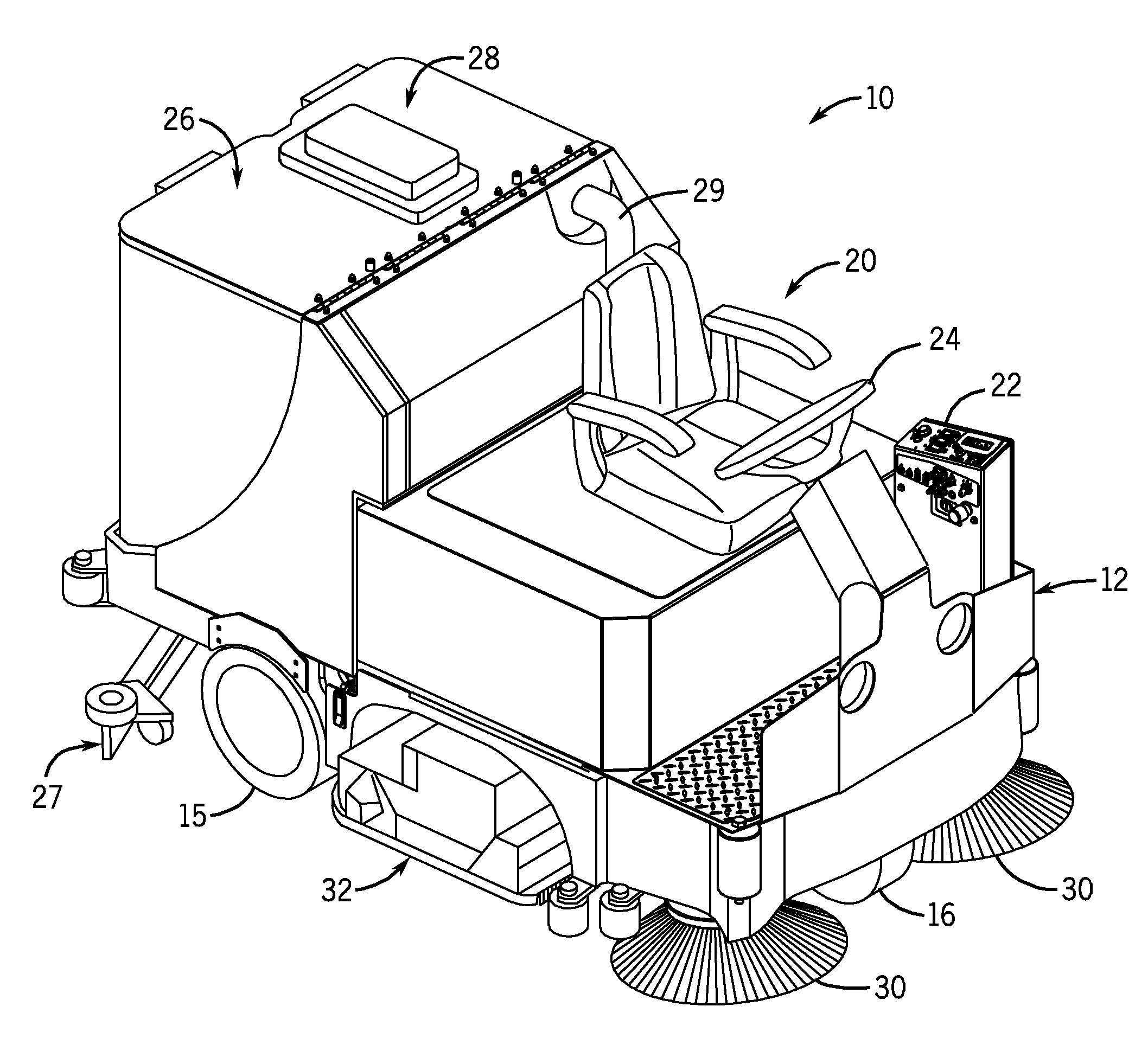
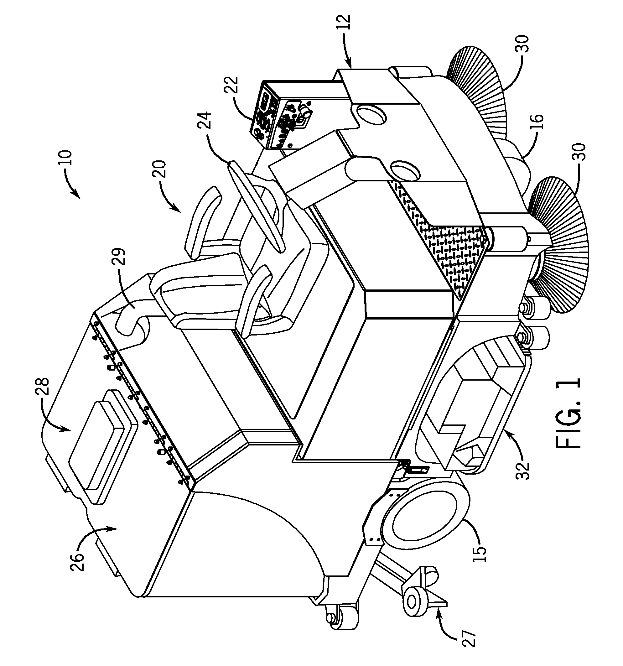
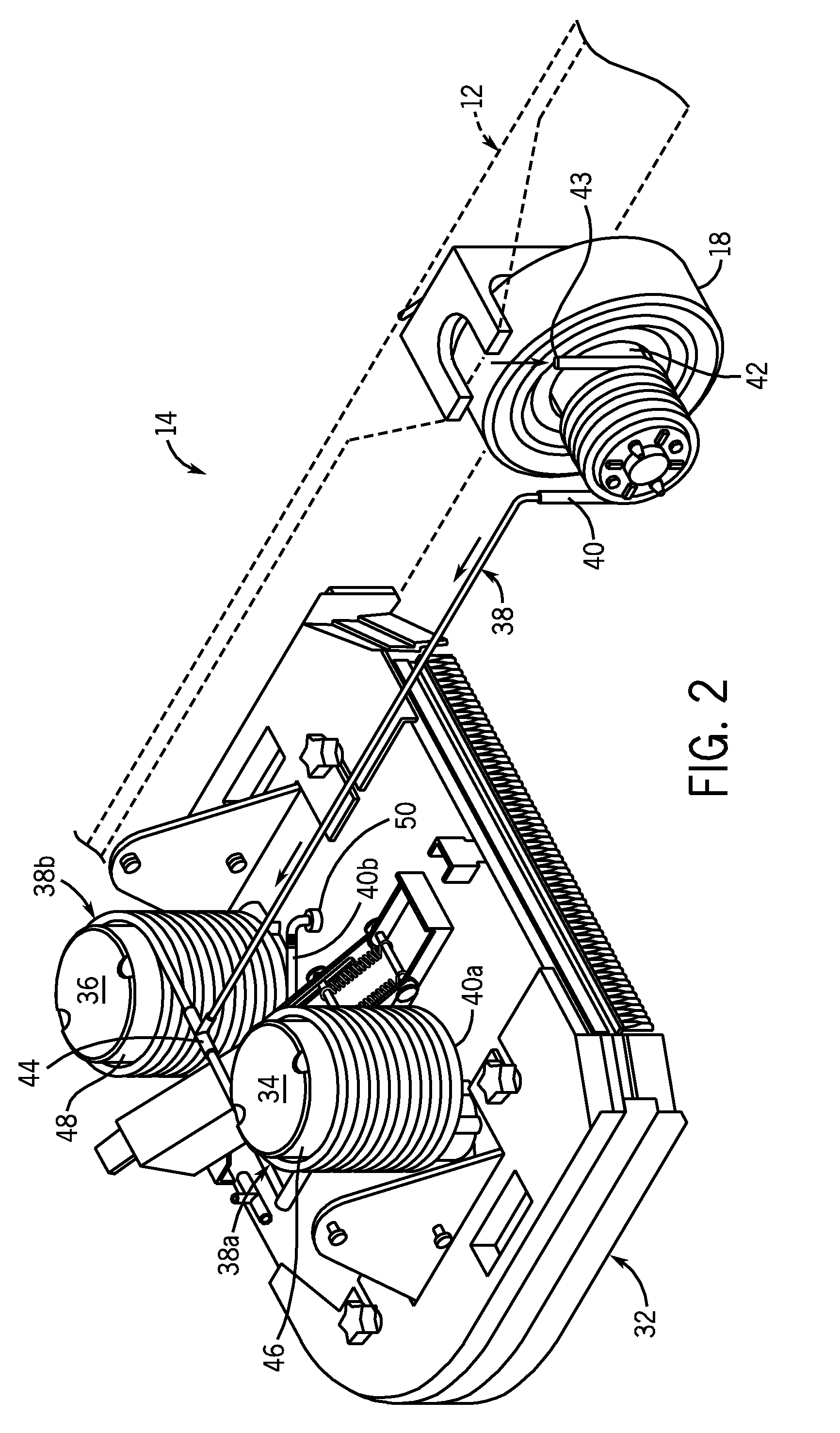
[0021]A cleaning device 10, in the form of a floor scrubber, is shown in FIG. 1. While the example cleaning device 10 is depicted and described as a ride-on floor scrubber, the various aspects of the fluid heating system 14 (an example of which is shown in simplified form in FIG. 2) are similarly applicable to other types and styles of cleaning devices. For example, the general fluid heating system 14 is equally applicable for use with sweepers that collect debris. Additionally, the cleaning device may be self-propelled (e.g., ride-on and walk-behind), push- or pull-type (e.g., either by an operator or another vehicle), or any combination thereof.

[0022]With continued reference to FIG. 1, the example cleaning device 10 is shown as a ride-on floor scrubber. The cleaning device 10 includes a frame 12 that supports a pair of rear wheels 15 and a single front wheel 16. The front wheel 16 is both driven by a drive motor 18 (shown in FIG. 2) and steerable. An operator compartment 20 includ...


PUM


Abstract

A cleaning device comprises a frame and a tank carried by the frame that contains a cleaning fluid. A first motor is capable of generating a first motor heat. A passageway is in fluid communication with the tank and is in thermal communication with the first motor to transfer at least a portion of the first motor heat to the cleaning fluid when the cleaning fluid is directed downstream from the tank through the passageway. An outlet is in fluid communication with the passageway and downstream of the first motor to direct the cleaning fluid onto a surface to be cleaned.

Description

CROSS REFERENCES TO RELATED APPLICATIONS[0001]Not Applicable.STATEMENT REGARDING FEDERALLY SPONSORED RESEARCH[0002]Not Applicable.BACKGROUND OF THE INVENTION[0003]The present invention relates generally to cleaning devices, and more particularly to a fluid heating system for use in a cleaning device.[0004]Cleaning devices are available to perform a variety of functions in various settings. For example, a self-propelled floor scrubber may be used to clean and maintain a factory floor. The floor scrubber may include a variety of implements, that is, brooms, scrubbers, vacuums, and the like to perform the cleaning operations. As another example, a walk-behind sweeper may be used to gather debris using a combination of sweepers and vacuums. Cleaning devices also come in a variety of drive types, such as, self-propelled (both walk behind and ride-on) and push- or pull-type, and often use an electric power source (e.g., batteries) to drive electric motors. Alternatively, or in addition to...

Claims


Application Information

Patent Timeline
Patent Type & Authority Applications(United States)
IPC IPC(8): B08B3/10
CPCA47L11/305A47L11/4088A47L11/4083
Inventor GOFF, SEAN K.
Owner RPS ,
Why Eureka
Try Eureka