Imaging system and method

a technology of imaging system and detector, applied in the field of radar imaging system and method, can solve the problems of inconvenient application, inconvenient processing, and inability to quickly adapt detectors to applications, and achieve the effect of improving range resolution

Active Publication Date: 2010-09-02
E2V TECH (UK) LTD
View PDF21 Cites 55 Cited by
  • Summary
  • Abstract
  • Description
  • Claims
  • Application Information

AI Technical Summary

Benefits of technology

[0080]Where a frequency division multiplexing scheme is utilised to transmit the pulses, a constant frequency separation is employed between the carrier frequencies of each pulses (i.e. the spacing between the carrier frequencies of each pulse in the frequency domain is identical). Preferably a variety of pulse compression techniques such as step-frequency range compression can be employed to further improve range resolution.

Problems solved by technology

This process can be quite time consuming where large numbers are to be screened, and the body contact can be considered some people to be both intrusive and offensive.
Thus such detectors are not readily suited to applications where screening at a distance is desirable.
Furthermore the detectors are only cable of detecting metal objects and fail to detect objects composed of ceramics e.g. ceramic knives, plastics or the like which can be a security concern.
X-rays have proved effective but are not acceptable in public places because of their inherent radiation hazard.
These mechanical scanning systems are unable to obtain fine image resolution at distant ranges.
This is because a relatively larger scanner is required and it is not feasible to scan these large antennas at the required speed.
Mechanically scanned systems also have a problem with achieving a fast enough refresh rate to capture images of a walking person.
Another problem with mechanically scanned antennas is that they only focus at one distance and with a narrow depth of focus.
Yet another problem with radiometer systems is their susceptibility to the natural sources of radiation which can be very variable and affect the image contrast.
Radar imaging systems provide a more consistent illumination of the object to be imaged and phased array radar technology has the potential to provide images with multiple depths of focus, at longer ranges, and with fast refresh times. However a conventional phased array requires the whole aperture to be filled with transmitter and receiver mm wave elements, leading to an excessive cost.
Whilst this describes a process for imaging in the near field, their approach is not suited to applications where objects being imaged might move during the process of collecting data from all the pair combinations in turn.
However the technique of synthesising a filed array in this manner is only applicable to the far field and will not focus in the near field.
The technique described in WO 2007 / 045026 is not able to image a walking person for security screening applications.
This corrupts the focussing process.
This process of synthesising virtual elements and using these for imaging is not valid in the near field.

Method used


Image

  • Imaging system and method
  • Imaging system and method
  • Imaging system and method

Examples


Embodiment Construction

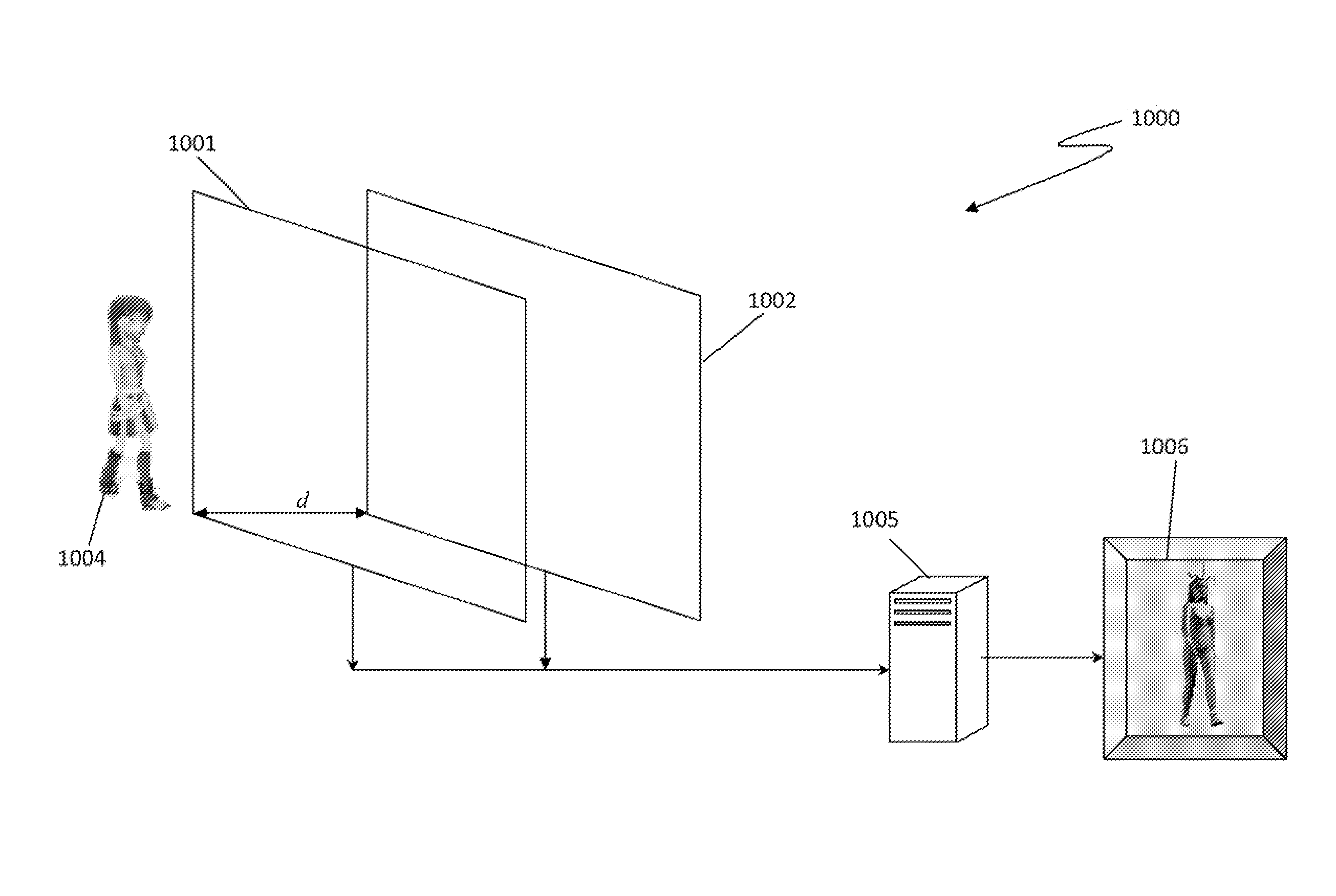
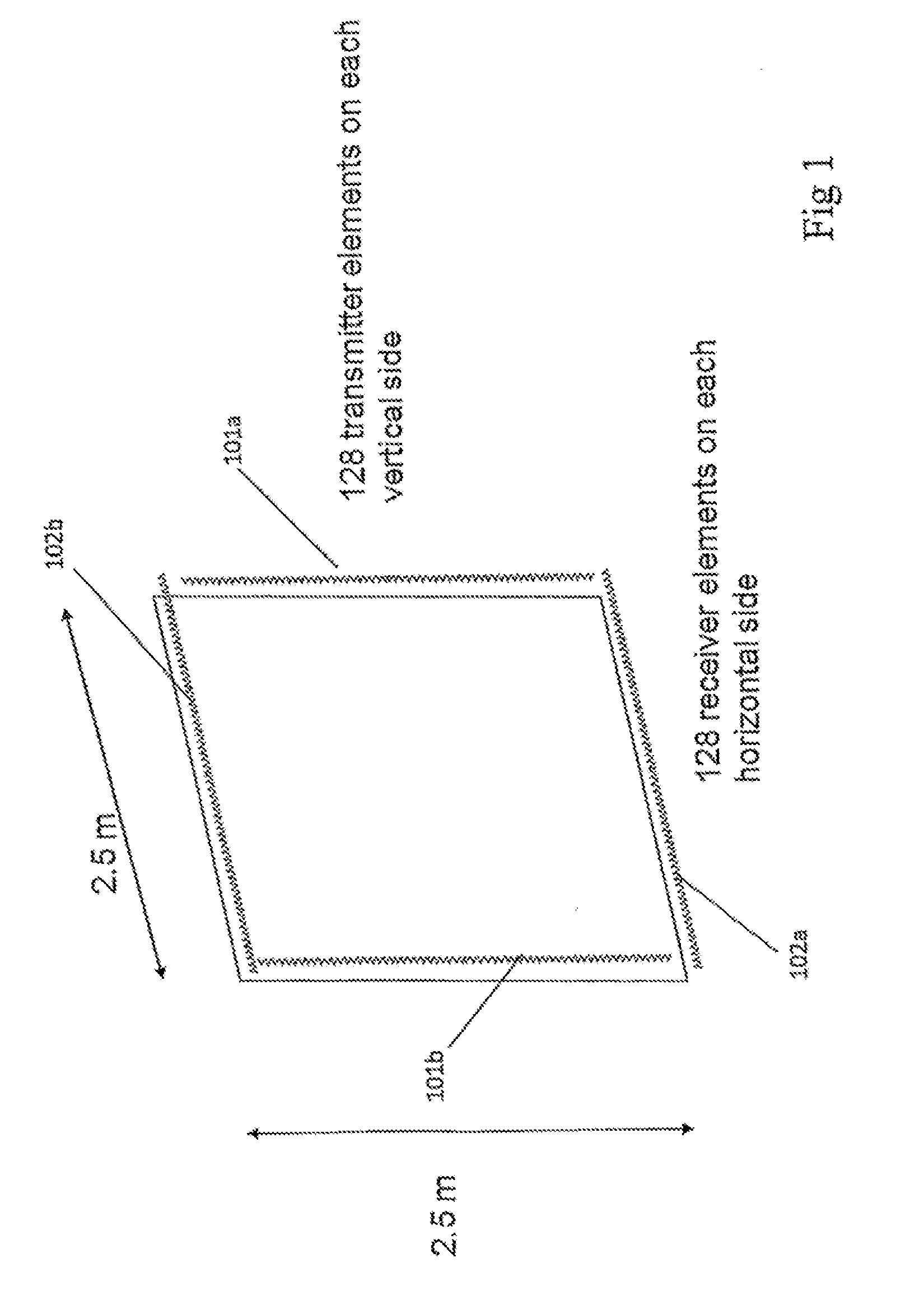
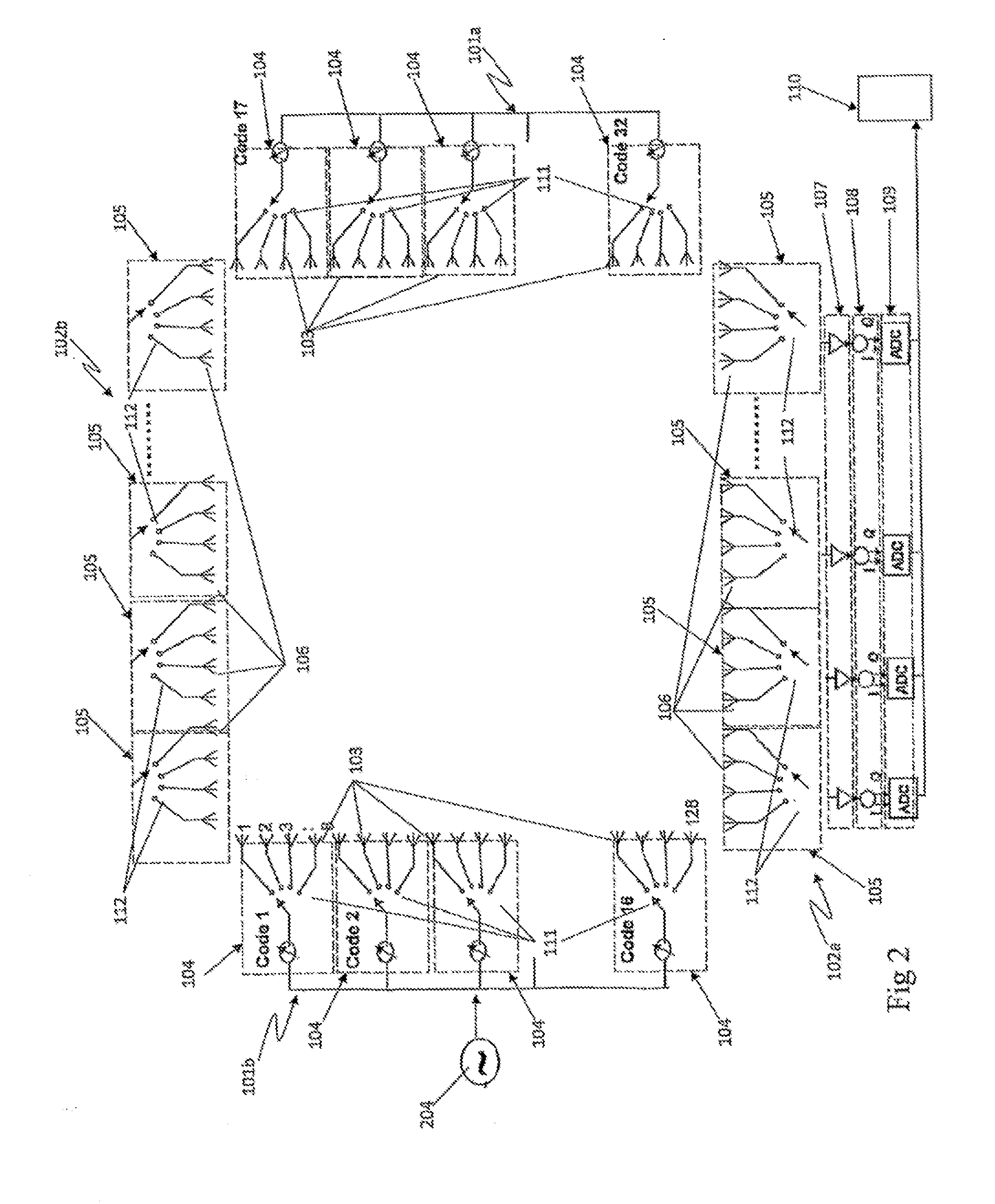
[0102]An example of one possible configuration of an imaging system according to one embodiment of the present invention is shown in FIG. 1. In this particular example the system is composed of a square perimeter antenna array 2.5×2.5 m nominal size. Disposed along each vertical edge 101a, 101b of the array is a set of N transmitter elements, with a set of M receiver elements being disposed along each horizontal edge 102a, 102b of the array. In this case each vertical transmitter sub-arrays contains 128 transmitter elements, likewise each horizontal receiver sub-arrays contains 128 receiver elements.

[0103]While the array shown in FIG. 1 is a square parameter array it will be appreciated by those skilled in the art that the array may be in the form of any suitable shape where multiple combinations of transmitter / receiver pairs allow the formation of a filled aperture. Such configurations might include a rectangle, parts of a rectangle forming a cross or L shape, a circle, octagon, or...


PUM


Abstract

A radar imaging system for capturing an image of an object within an area of interest through at least one visual impairment. The radar imaging system comprises at least one radar array. The radar array includes a plurality of transmitter elements and a plurality of receiver elements for receiving a plurality of coded return signals from an object through the at least one visual impairment. The system further comprises at least one processor coupled to the transmitter and receiver elements, which is adapted to transmit a plurality of differently coded signals toward the object and the at least one visual impairment; decode the plurality of coded return signals received by each of the receiver elements; extract from the decoded return signals a multiplicity of captured signals for each transmitter to receiver path; focus the multiplicity of signals on all points of interest within the area of interest by aligning the multiplicity of captured signals to be co-incident from a particular point within the area of interest; and sum the aligned signals to produce an image of the object. A method for capturing an image of an object in an area of interest through at least one visual impairment is also provided.

Description

CROSS REFERENCE TO PRIOR APPLICATIONS[0001]This application is a continuation of International Application PCT / AU2008 / 001386, published as WO 2009 / 036507, with an international filing date of Sep. 18, 2008, which claims priority from Australian Patent Application No. 2007 / 905114, filed Sep. 19, 2007, all of which are hereby incorporated by reference for all purposes as if fully set forth hereinBACKGROUND OF THE INVENTION[0002]1. Field of the Invention[0003]The present invention relates to a radar imaging system and method for real-time or near real-time video imaging. In particular although not exclusively the present invention relates to a radar imaging system and method, for security screening and the like.[0004]2. Discussion of the Background Art[0005]Persons entering highly secure areas are often required to undergo some form of screening to ensure weapons or explosives are not being carried. These security concerns have led to the development of various techniques designed to d...

Claims


Application Information

Patent Timeline
Patent Type & Authority Applications(United States)
IPC IPC(8): G01S13/00
CPCG01S7/414G01S13/003G01S13/48G01S13/87H01Q25/00G01S13/89H01Q1/007H01Q21/0006H01Q21/08G01S13/887G01S13/347
Inventor LONGSTAFF, IAN DENNIS
Owner E2V TECH (UK) LTD
Why Eureka
Try Eureka