Surveillance Apparatus and Method

a technology of surveillance apparatus and antenna, applied in the field of surveillance apparatus and method, can solve the problems of increasing the number of elements populating the radar aperture, prone to wind loading effects, and exceedingly difficult to mount on board ships and other moving vehicles, so as to facilitate the design of a radar and improve the range resolution. , the effect of high range resolution

Active Publication Date: 2010-07-01
E2V TECH (UK) LTD
View PDF15 Cites 42 Cited by
  • Summary
  • Abstract
  • Description
  • Claims
  • Application Information

AI Technical Summary

Benefits of technology

[0041]Suitably, where a frequency division multiplexing scheme is utilized to transmit the pulses, a constant frequency separation is employed between the carrier frequencies of each pulse (i.e. the spacing between the carrier frequencies of each pulse in the frequency domain is identical). Preferably a variety of pulse compression techniques such as step-frequency range compression can be employed to further improve range resolution. In this instance the step frequency technique facilitates the design of a radar with high range resolution, with low instantaneous bandwidth, the trade off being a long observation period to allow transmission of all the frequency steps.
[0042]Alternatively, where code division multiplexing is used to transmit the pulses, differing code sequences can be simultaneous transmitted, using codes which are separable at the receivers for beamforming. Such codes allow pulse compression as well as facilitating the beamforming process. Sets of code sequences which produce low or zero range sidelobes, may be utilized to reduce leakage into the other channels when separated for the beamforming process. Employing such a CDM scheme form allows the radar image to be synthesized from a single simultaneous burst of the differing codes.
[0043]Alternatively the transmitters may transmit a plurality of signal pulses utilizing time division multiplexing (TDM), wherein the time delay between successive transmitted pulses is of sufficient length to allow to reception of return signals reflected by one or more objects within range. Utilizing a TDM transmission scheme the design of the radar can be greatly simplified as it allows the signal from a single transmitter amplifier is switched sequentially to each transmitter element, the trade-off is that a long observation time is required to complete the transmission sequence.

Problems solved by technology

However a problem with such planar arrays is that they tend to be rather large and cumbersome and prone to wind loading effects, especially in mobile applications.
The size and weight of planar arrays generally results from the number of elements populating the radar aperture.
This makes them exceedingly difficult to mount on board ships and other moving vehicles.
Furthermore the cost of producing such arrays is rather prohibitive and accordingly the use of such arrays has all but been limited, for example to a few military applications.
Another problem with the use of a planar phased array is that it typically only covers + / −45 degrees from the bore-sight.

Method used


Image

  • Surveillance Apparatus and Method
  • Surveillance Apparatus and Method
  • Surveillance Apparatus and Method

Examples


Embodiment Construction

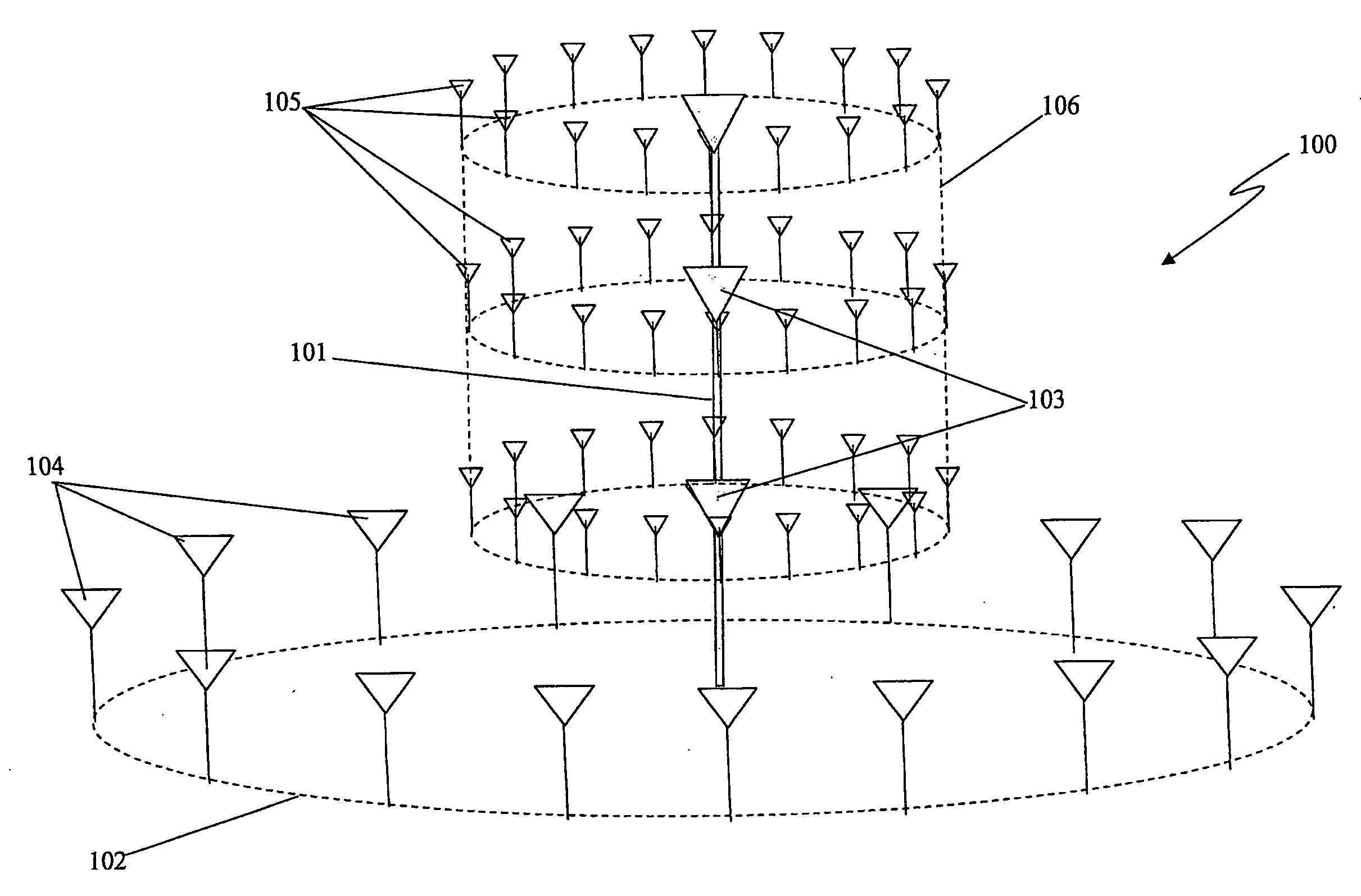
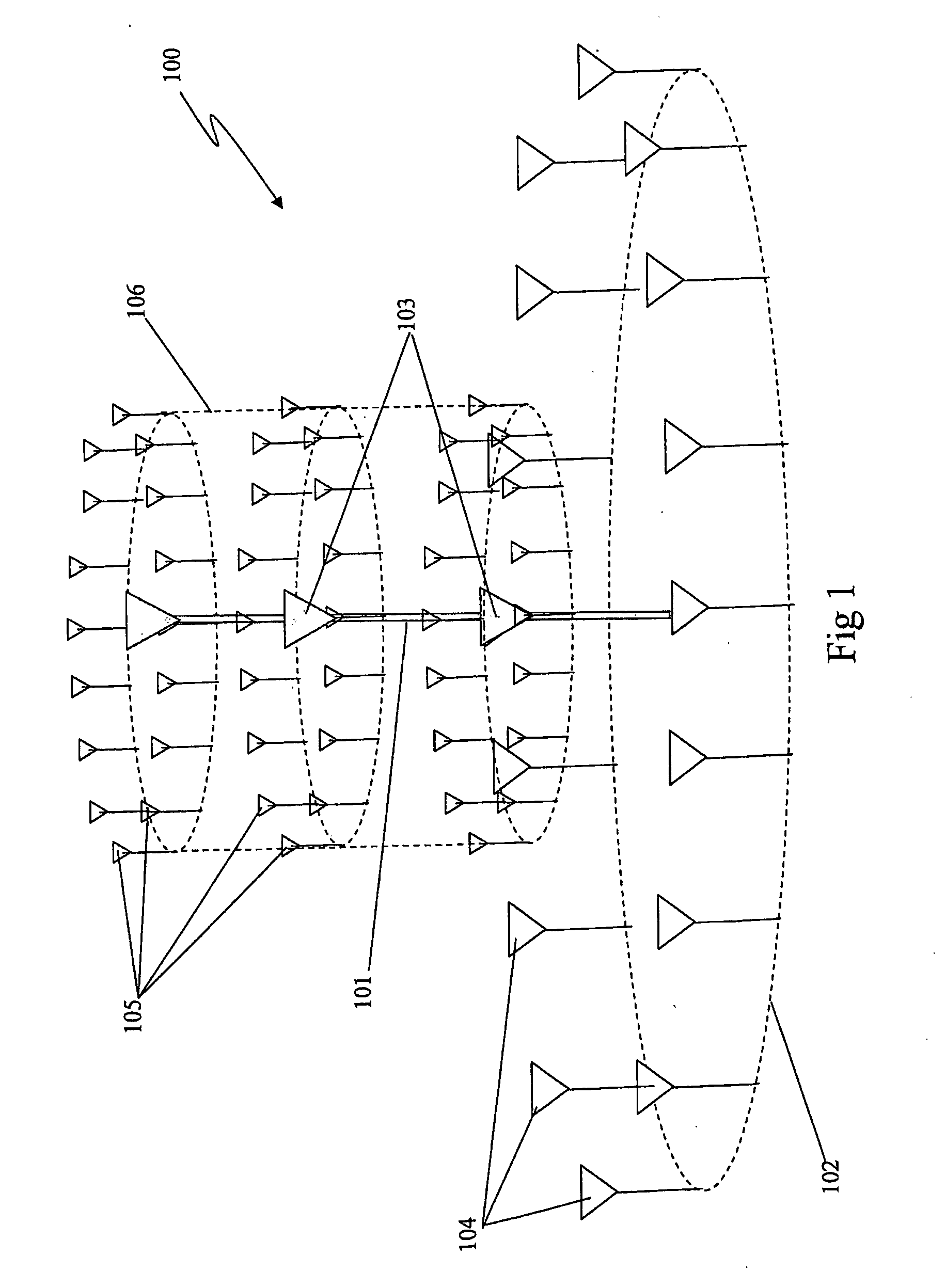
[0092]With reference to FIG. 1 there is illustrated one possible configuration of a phased array 100 according to an embodiment of the present invention. The diagram shows the positions of the transient elements which together with the physical elements, notionally form a synthetic array for processing targets in the far field.

[0093]The array 100 in this instance comprises a linear sub-array 101 of N omnidirectional transmitter elements and a planar sub-array 102 of M receiver elements. In this particular instance the M receivers are arranged in a circular array about the linear sub-array. Such a configuration enables a full 360 degrees of cover in azimuth and typically + / −60 degrees in elevation. It will be appreciated by those of ordinary skill in the art that the planar sub-array need not be a circular array but may take the form of any other suitable planar shape such as a square, rectangle, triangle etc.

[0094]The process of generating transient elements makes use of the fact th...


PUM


Abstract

A surveillance apparatus (100) is provided, said apparatus including a linear sub-array (101) of N omnidirectional transmitter elements (103) and a planar sub-array (102) of M receiver elements (104). A plurality of the transient elements (105) are generated by separating out at each of the receivers (104) the signals transmitted from the antenna elements (103) of the transmitter sub-array (101). This allows the geometry of each path (from each transmitter antenna element, to the point being imaged and back to the receiver antenna elements) to be converted to a delay or phase shift to focus on the particular point being imaged. The transient elements (105) form a cylindrical array (106) at the mid points between transmitter and receiver sub-arrays. Such a configuration enables a full 360 degrees of cover in azimuth and typically +/−60 degrees in elevation.

Description

BACKGROUND OF THE INVENTION[0001]1. Field of the Invention[0002]The present invention relates to a surveillance apparatus and method. In particular, although not exclusively, the present invention relates to radar systems including phased array radar systems.[0003]2. Discussion of the Background Art[0004]The principles of phased arrays have been utilized in a number of fields including telecommunications (e.g. AM broadcast stations), radio astronomy and radar systems since the Second World War. Typically such arrays include a number of active radiators coupled to a feed network. The phase of each feed signal supplied to each of the radiators is varied in such a way that the effective radiation pattern of the array is reinforced in a desired direction (i.e. directional beam), while being suppressed in undesired directions.[0005]One type of phased array radar is a planar phased array which has good resolution and overcomes the limitations of mechanically scanned antennas. An example o...

Claims


Application Information

Patent Timeline
Patent Type & Authority Applications(United States)
IPC IPC(8): G01S13/00H01Q21/00
CPCG01S13/003G01S13/06G01S13/284H01Q21/08H01Q21/205H01Q21/24G01S13/347
Inventor LONGSTAFF, DENNIS
Owner E2V TECH (UK) LTD
Why Eureka
Try Eureka