
Collision avoidance system and method

a technology of collision avoidance and avoidance system, which is applied in the direction of distance measurement, instruments, and using reradiation, can solve the problems that systems are not readily suited to use in unmanned air vehicles and the like, and achieve the effects of improving range resolution, avoiding and minimizing the effect of doppler on pulse compression

Inactive Publication Date: 2010-08-12
TELEDYNE AUSTRALIA
View PDF46 Cites 70 Cited by
  • Summary
  • Abstract
  • Description
  • Claims
  • Application Information

AI Technical Summary

Benefits of technology

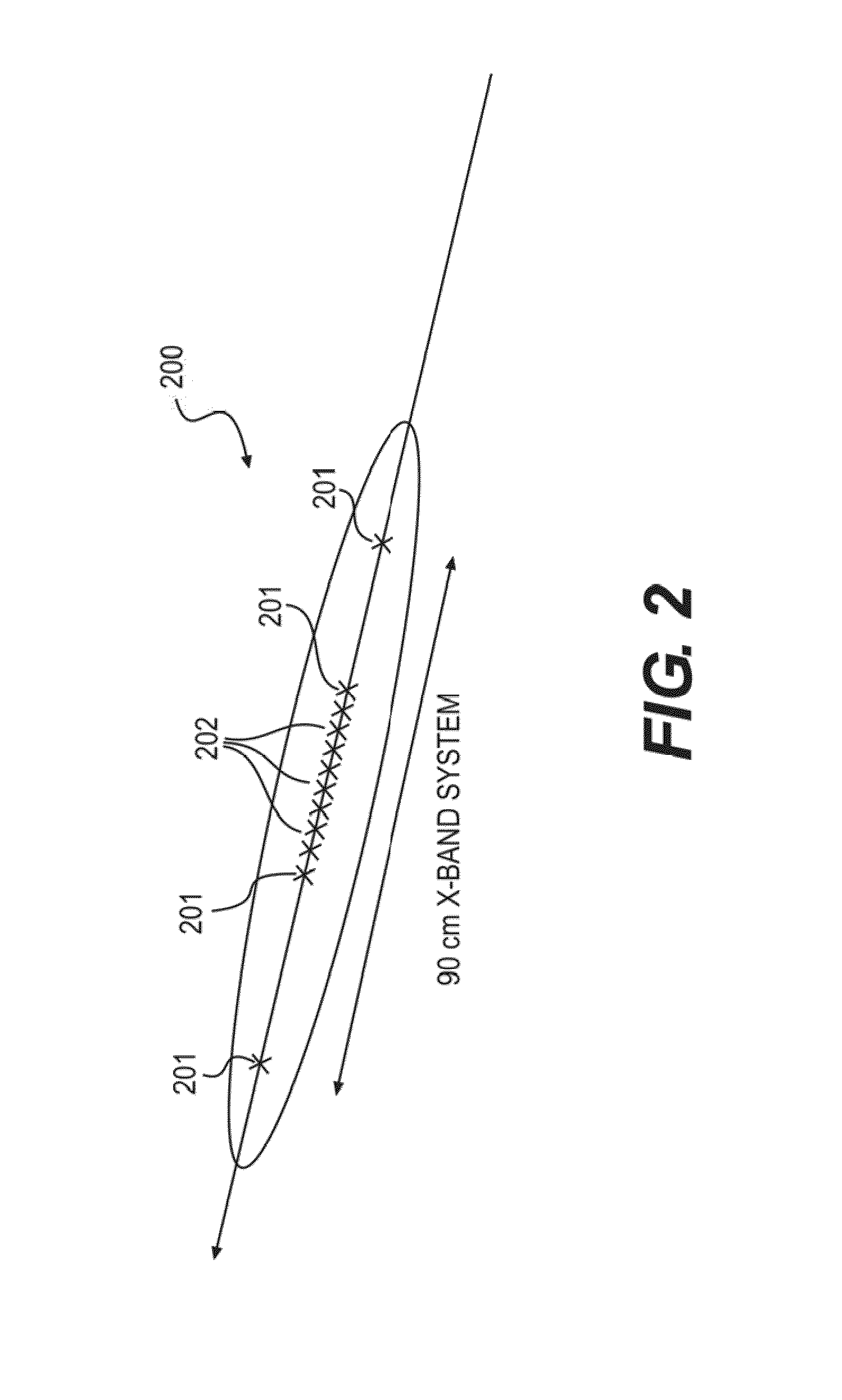
[0056]Where a frequency division multiplexing scheme is utilised to transmit the pulses, a constant frequency separation is employed between the carrier frequencies of each pulses (i.e. the spacing between the carrier frequencies of each pulse in the frequency domain is identical). Preferably a variety of pulse compression techniques such as step-frequency range compression can be employed to further improve range resolution. The sequence of frequencies so transmitted can be ordered according to certain codes to minimise the effect of Doppler on pulse compression. An example of such an ordered code set is that of Costas codes which set the hopping sequence for the frequency steps and improves the range / Doppler ambiguity

Problems solved by technology

As can be seen from the above discussion both transponder systems rely on the pilot of the aircraft to take the appropriate action to avoid collision, such systems are not readily suited to use in unmanned air vehicles and the like.

Method used


Image

  • Collision avoidance system and method
  • Collision avoidance system and method
  • Collision avoidance system and method

Examples


Embodiment Construction

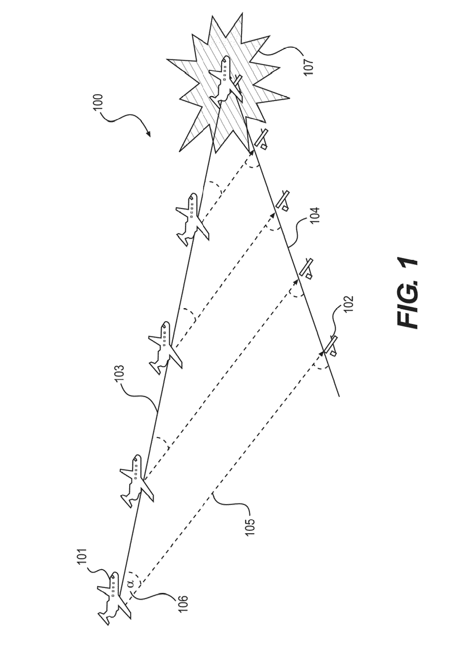
[0084]FIG. 1 depicts the basic geometry of a collision 100 between two vehicles. In this instance a first aircraft 101 on a first flight path 103 and a second unmanned aircraft 102 on a second flight path 104. The line of sight between each aircraft remains constant as does the relative angle α106. As the aircraft continue along their respective flight paths the range 105 between the two is reduced at a constant rate and it is this constant reduction in range or constant relative angle α106 that indicates a potential collision threat 107. Thus in order to avoid the collision 107 one of the aircraft 102 needs to alter course (i.e. change the relative angle α106 between the two). However the aircraft cannot just simply alter tact, any course correction must be negotiated in accordance with the rules for a given airspace.

[0085]As discussed above, one of the factors inhibiting development and usage of unmanned vehicles is the lack of a collision avoidance system that provides such vehic...


PUM


Abstract

A collision avoidance system for use with an unmanned vehicle, the system includes a plurality of radar elements arranged parallel to the longitudinal axis of the unmanned vehicle, wherein the radar elements transmit a plurality of pulses about the vehicle and receive a plurality of return signals from one or more objects within the range of the vehicle. Upon detecting the one or more objects within range of the vehicle, the system determines if an object is on a course which requires evasive action and suitably alters the vehicle's course in order to avoid collision.

Description

CROSS REFERENCE TO PRIOR APPLICATIONS[0001]This application is a continuation of International Application PCT / AU2008 / 000628, published as WO 2008 / 134815, with an international filing date of May 2, 2008, which claims priority from Australian Patent Application No. 2007 / 902404, filed May 4, 2007, all of which are hereby incorporated by reference for all purposes as if fully set forth herein.BACKGROUND OF THE INVENTION[0002]1. Field of the Invention[0003]The present invention relates to a collision avoidance system and method. In particular although not exclusively the present invention relates to a collision avoidance system for unmanned air vehicles or the like.[0004]2. Discussion of the Background Art[0005]Collision avoidance systems have been employed in a wide variety of applications ranging from simple range detection, similar to that used in parking sensors employed in most high-end automobiles, to more sophisticated applications such as aircraft mid air warning systems.[0006]...

Claims


Application Information

Patent Timeline
Patent Type & Authority Applications(United States)
IPC IPC(8): G01S13/93G05D1/00G01S13/933
CPCG01S13/003G01S13/9303H01Q21/0043H01Q13/22G01S13/94G01S13/935G01S13/933
Inventor LONGSTAFF, DENNIS
Owner TELEDYNE AUSTRALIA
Learn More