
High resolution SAR processing using stepped-frequency chirp waveform

a chirp waveform and high-resolution technology, applied in the field of radar systems, can solve the problems of not being practical for general high-resolution sar systems, the limit of range resolution that can be achieved by conventional processing of sar data, etc., and achieve the limit of range resolution, improve range resolution, and limit the effect of range resolution

Inactive Publication Date: 2005-11-15
THE GOVERNMENT OF THE US SEC THE AIR FORCE
View PDF9 Cites 30 Cited by
  • Summary
  • Abstract
  • Description
  • Claims
  • Application Information

AI Technical Summary

Benefits of technology

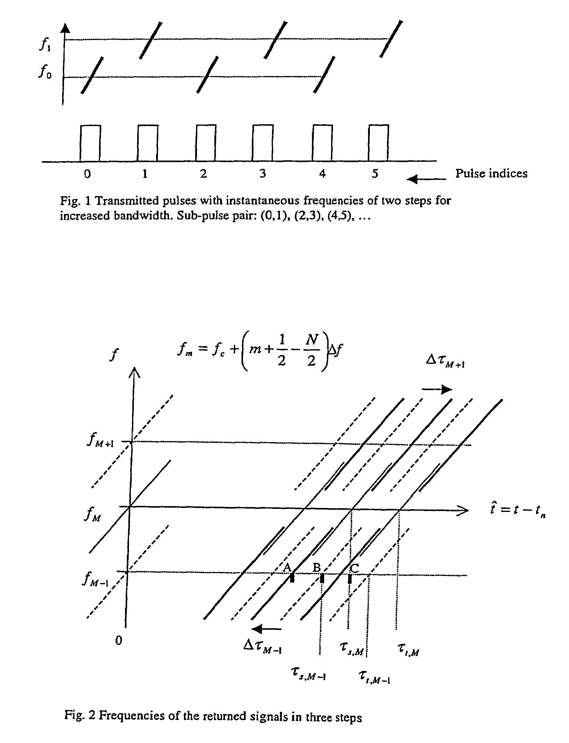
[0011]Range resolution in SAR image is inversely proportional to the transmitted signal bandwidth in nominal SAR systems. Since there is a limit in the transmitted bandwidth that can be supported by the radar hardware, there is a limit in range resolution that can be achieved by processing SAR data in conventional manner. However, if the frequency band of the transmitted signal is skipped within a group of sub-pulses and received signal is properly combined, the composite signal has effectively increased the bandwidth and hence improvement in range resolution can be achieved. The proposed new and practical approach can effectively extend the limit in range resolution beyond the level that is set by the radar hardware units when conventional method is used.
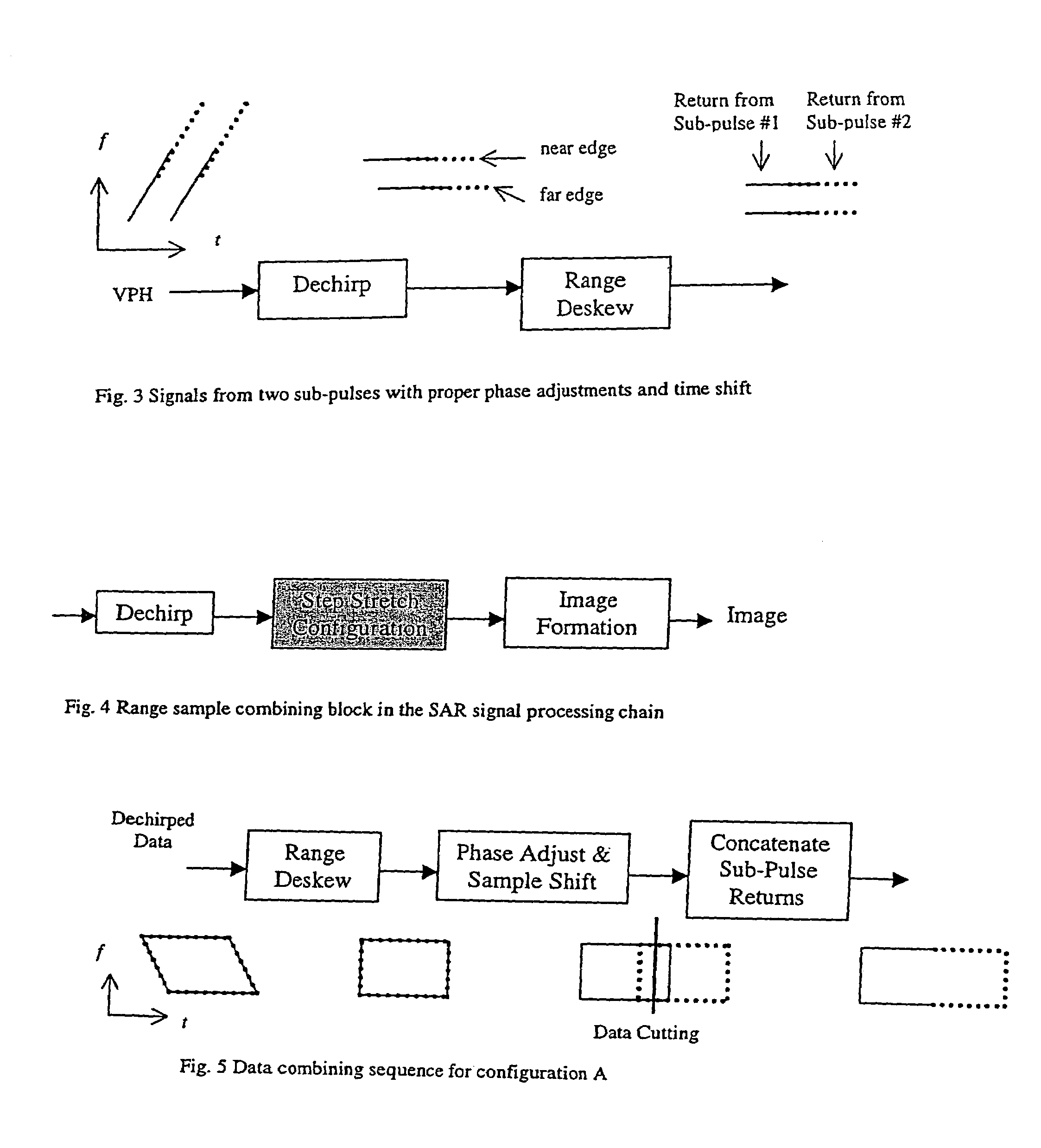
[0018]4. Data cutting and concatenating to minimize the error effect around the step boundaries

Problems solved by technology

Since there is a limit in the transmitted bandwidth that can be supported by the radar hardware, there is a limit in range resolution that can be achieved by processing SAR data in conventional manner.
They all tried to combine data before dechirp processing and it is not considered to be practical for general high resolution SAR systems since dechirp function for high resolution mode is performed before A / D conversion.

Method used


Image

  • High resolution SAR processing using stepped-frequency chirp waveform
  • High resolution SAR processing using stepped-frequency chirp waveform
  • High resolution SAR processing using stepped-frequency chirp waveform

Examples


Embodiment Construction

[0028]The present invention includes process for use with SAR, systems that uses a stepped-frequency chirp waveform during groundmapping.

[0029]Range resolution in SAR images is determined by the radar bandwidth: range resolution is inversely proportional to the radar bandwidth. Therefore, for very high resolution in range, radar bandwidth of the SAR system is required to be very large. To meet the requirement of desired minimum average power with limited peak power, stretched pulse with linear frequency modulation (LFM) is widely used in SAR systems. As the radar bandwidth increases, hardware performance degrades and there is a limit on bandwidth that radar hardware such as antenna and receiver can support. Natural approach under this situation where very high range resolution requirement cannot be met due to hardware limitation is to transmit sub-pulses that have varying center frequencies with limited bandwidth and combine the return for each sub-pulse so that increased bandwidth ...


PUM


Abstract

A stepped-frequency chirped waveform improves SAR groundmapping for the following reasons. Range resolution in SAR image is inversely proportional to the transmitted signal bandwidth in nominal SAR systems. Since there is a limit in the transmitted bandwidth that can be supported by the radar hardware, there is a limit in range resolution that can be achieved by processing SAR data in conventional manner. However, if the frequency band of the transmitted signal is skipped within a group of sub-pulses and received signal is properly combined, the composite signal has effectively increased bandwidth and hence improvement in range resolution can be achieved. The proposed new and practical approach can effectively extend the limit in range resolution beyond the level that is set by the radar hardware units when conventional method is used.

Description

STATEMENT OF GOVERNMENT INTEREST[0001]The invention described herein may be manufactured and used by or for the Government for governmental purposes without the payment of any royalty thereon.BACKGROUND OF THE INVENTION[0002]The present invention relates generally to radar systems and more specifically to a waveform process for use with radar systems.[0003]A Synthetic Aperture Radar (SAR) system is used for ground mapping even in poor weather conditions in which optical sensor cannot be used. Mapping range of SAR is generally longer than optical sensor and it can also be operated during night. Using SAR, desired resolution in azimuth is achieved by maintaining phase coherence between pulses and combining them in proper manner. The length of collected data (array length) is determined by desired azimuth resolution and collection geometry.[0004]The following references disclose recent SAR systems that can be used with the present invention and the disclosures of which are incorporated...

Claims


Application Information

Patent Timeline
Patent Type & Authority Patents(United States)
IPC IPC(8): G01S13/38G01S13/00G01S13/90G01S13/24G01S13/28
CPCG01S13/24G01S13/282G01S13/9035G01S13/904
Inventor CHO, KWANG MYUNGHUI, LEO H.
Owner THE GOVERNMENT OF THE US SEC THE AIR FORCE
Learn More