Backlight apparatus and display apparatus

a backlight apparatus and display device technology, applied in the field of backlight apparatus and display device, can solve the problems of black becoming bright, difficulty in making the number of divisions of the backlight, etc., and achieve the effect of reducing the number of divisions and ensuring the quality of the imag

Active Publication Date: 2010-09-02
PANASONIC CORP
View PDF6 Cites 46 Cited by
  • Summary
  • Abstract
  • Description
  • Claims
  • Application Information

AI Technical Summary

Benefits of technology

[0019]According to the present invention, it is possible to provide a backlight apparatus and display apparatus that allow brightness control with minimum image quality deterioration.

Problems solved by technology

With the configuration as described above, in terms of cost, it is difficult to make the number of divisions of the backlight (i.e. the resolution of the backlight) the same as the resolution of the optical modulating section.
Therefore, problems occur due to the difference in resolution between the backlight and the optical modulating section.
One of the problems is the phenomenon where a part that must be displayed in black becomes bright and appears distinctly (hereinafter, “black floating”).

Method used


Image

  • Backlight apparatus and display apparatus
  • Backlight apparatus and display apparatus
  • Backlight apparatus and display apparatus

Examples


embodiment 1

[0051]Hereinafter, Embodiment 1 (an embodiment of applying weights to reference brightness values), which is an example where the present invention is applied to a liquid crystal display apparatus, will be explained with reference to the accompanying drawings.

[0052]

[0053]First, the configuration of the liquid crystal display apparatus will be explained.

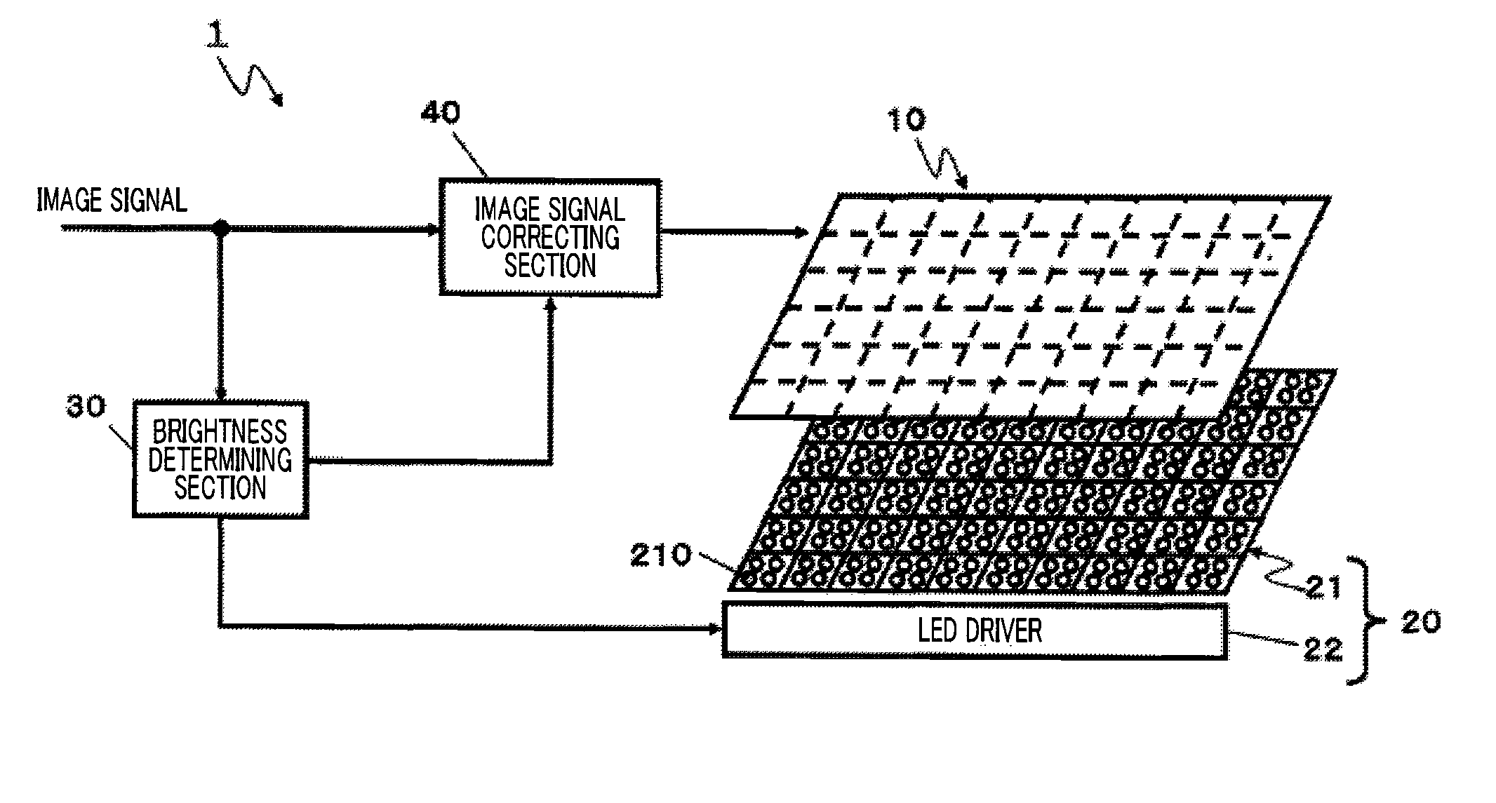
[0054]FIG. 3 is a configuration diagram showing the overall configuration of the liquid crystal display apparatus. Roughly, liquid crystal display apparatus 1 has liquid crystal panel 10, illuminating section 20, brightness determining section 30, and image signal correcting section 40. Hereinafter, illuminating section 20 and brightness determining section 30 will be collectively referred to as “backlight.” The configuration of each section will be explained below in detail.

[0055]

[0056]Liquid crystal panel 10 modulates illumination light that is radiated on its back, according to an image signal, and displays an image.

[0057]Liquid cr...

embodiment 2

[0163]Next, Embodiment 2 (an embodiment of applying weights to reference feature amounts), which is an example where the present invention is applied to a liquid crystal display apparatus, will be explained with reference to the accompanying drawings. Embodiment 2 differs from Embodiment 1 in the configuration of brightness determining section 30 shown in FIG. 3. The configurations of the rest of the parts are the same as in Embodiment 1, and part of explanation will be omitted.

[0164]Note that, while reference brightness values calculated in the brightness calculating section are applied weights with Embodiment 1, feature amounts of an image signal prior to being inputted in the brightness calculating section are applied weights with Embodiment 2.

[0165]FIG. 23 is a configuration diagram showing the specific configuration of brightness determining section 30a. Roughly, brightness determining section 30a has feature detecting section 31a, temporary memory 33a, weighting section 34a an...

embodiment 3

[0182]Next, Embodiment 3 (i.e. mode 1 where weights with respect to a reference bright value are changed based on ambient light) which is an example where the present invention is applied to a liquid display apparatus will be explained with reference to the accompanying drawings. Embodiment 3 differs from Embodiment 1 in providing an ambient light detecting section in a brightness determining section. The configuration of other components is the same as in Embodiment 1, and explanation thereof will be omitted.

[0183]The above visibility of “black floating” part significantly changes depending on the condition of ambient light in the surroundings of the liquid crystal display apparatus. That is, in environment where the luminance of ambient light in the surroundings is low, for example, when an image is viewed in a very dark room, “black floating” is more likely to be seen. By contrast with this, in environment where the luminance of ambient light in the surroundings is high, for exam...


PUM


Abstract

The backlight apparatus allows brightness control with minimum image quality deterioration. This apparatus has: an illuminating section (20) that radiates illumination light on a back of a liquid crystal panel (10) which comprises a plurality of image display areas and which displays an image by modulating per image display area the illumination light according to an image signal; and a brightness determining section (30) that determines a light emission brightness value of the illuminating section (20) and renews a light emitting state of the illuminating section (20), based on the determined light emission brightness value, and the illuminating section (20) has a plurality of light emitting areas illuminating each of a plurality of image display areas, and the brightness determining section (30) determines a light emission brightness value of the first image display area, from values acquired by applying weights to the first information based on an input image signal of the first image display area and the second information based on the input image signal of the second image display areas, and changes the weights for the first information and the second information based on luminance of ambient light surrounding the backlight apparatus.

Description

CROSS REFERENCE TO RELATED APPLICATIONS[0001]This application is a continuation of International Patent Application No. PCT / JP2009 / 004854, filed on Sep. 25, 2009, the disclosure of which is incorporated herein by reference in its entirety. The disclosure of International Patent Application No. PCT / JP2009 / 004854, filed on Sep. 25, 2009, including the specification, drawings and abstract is incorporated herein by reference in its entirety.TECHNICAL FIELD[0002]The technical field relates to a backlight apparatus and a display apparatus using this backlight apparatus. More particularly, the technical field relates to a backlight apparatus and display apparatus for controlling the lighting of a plurality of divided areas.BACKGROUND ART[0003]Non-self-luminous display apparatuses represented by liquid crystal display apparatuses have backlight apparatuses (hereinafter, simply “backlight”) in the back. These display apparatuses display images through an optical modulating section. According...

Claims


Application Information

Patent Timeline
Patent Type & Authority Applications(United States)
IPC IPC(8): G09G3/36
CPCG02F2001/133601G09G2320/0646G09G3/3648G09G3/3426G09G2360/144G02F1/133601
Inventor YAMAMURA, AKIHIROKOBAYASHI, TAKAHIRONAKANISHI, HIDEYUKIONISHI, TOSHIKIHAMADA, SEIJINAKANISHI, ATSUSHI
Owner PANASONIC CORP
Why Eureka
Try Eureka