Broadcasting signal receiving system

a technology of receiving system and broadcasting signal, which is applied in the field of broadcasting signal receiving system, can solve the problems of limiting the effect of educationally undesirable programs on the viewer, not considering the prevention of a hyper-sensitivity to light that is liable to occur, and the generation of a hyper-sensitivity to light for children cannot be completely prevented

Inactive Publication Date: 2006-10-26
FUNAI ELECTRIC CO LTD
View PDF5 Cites 10 Cited by
  • Summary
  • Abstract
  • Description
  • Claims
  • Application Information

AI Technical Summary

Benefits of technology

[0014] According to the broadcasting signal receiving system of the present invention, the individual is certified by the certifying part so that the viewer can be automatically specified and the brightness of the room during viewing the program that has been usually controlled by the protector can be controlled even when the protector is not present. Thus, the generation of a hyper-sensitivity to light can be prevented that is apt to occur in such a case that infants view an animation program in a dark place.

Problems solved by technology

Further, in the device disclosed in JP-A-2001-16514, when the viewer is the infant or the minority, a program that gives the educationally undesirable effect to the viewer can be limited.
However, both the related arts do not consider a prevention of a hyper-sensitivity to light that is liable to occur when a child views an animation program in a dark place.
However, since viewing environments are different in homes respectively, the hyper-sensitivity to light for the children cannot be completely prevented only by the countermeasure of the production companies for producing the animations.

Method used


Image

  • Broadcasting signal receiving system
  • Broadcasting signal receiving system
  • Broadcasting signal receiving system

Examples


Embodiment Construction

[0019] Now, embodiments of the present invention will be described with reference to the drawings.

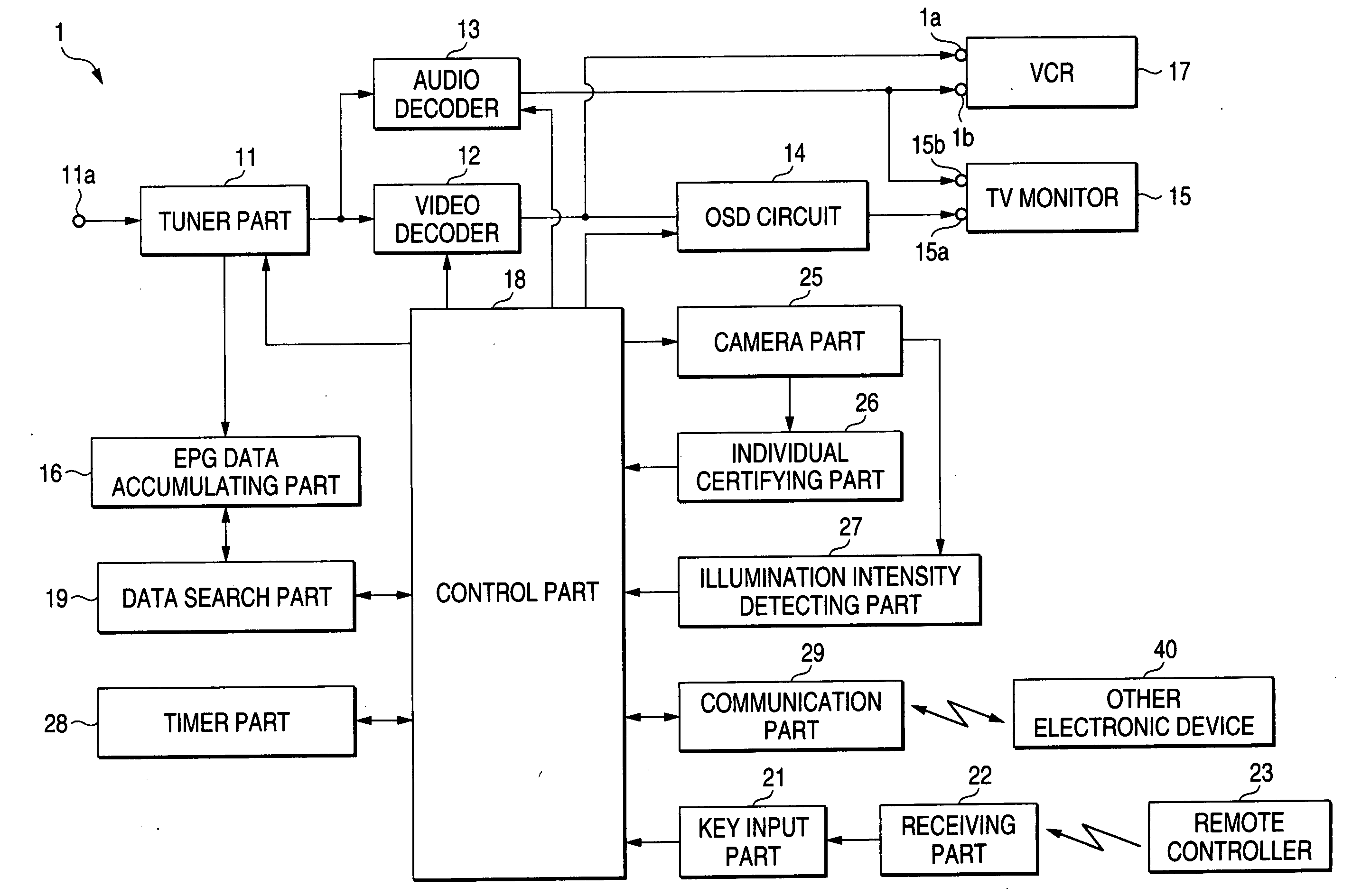
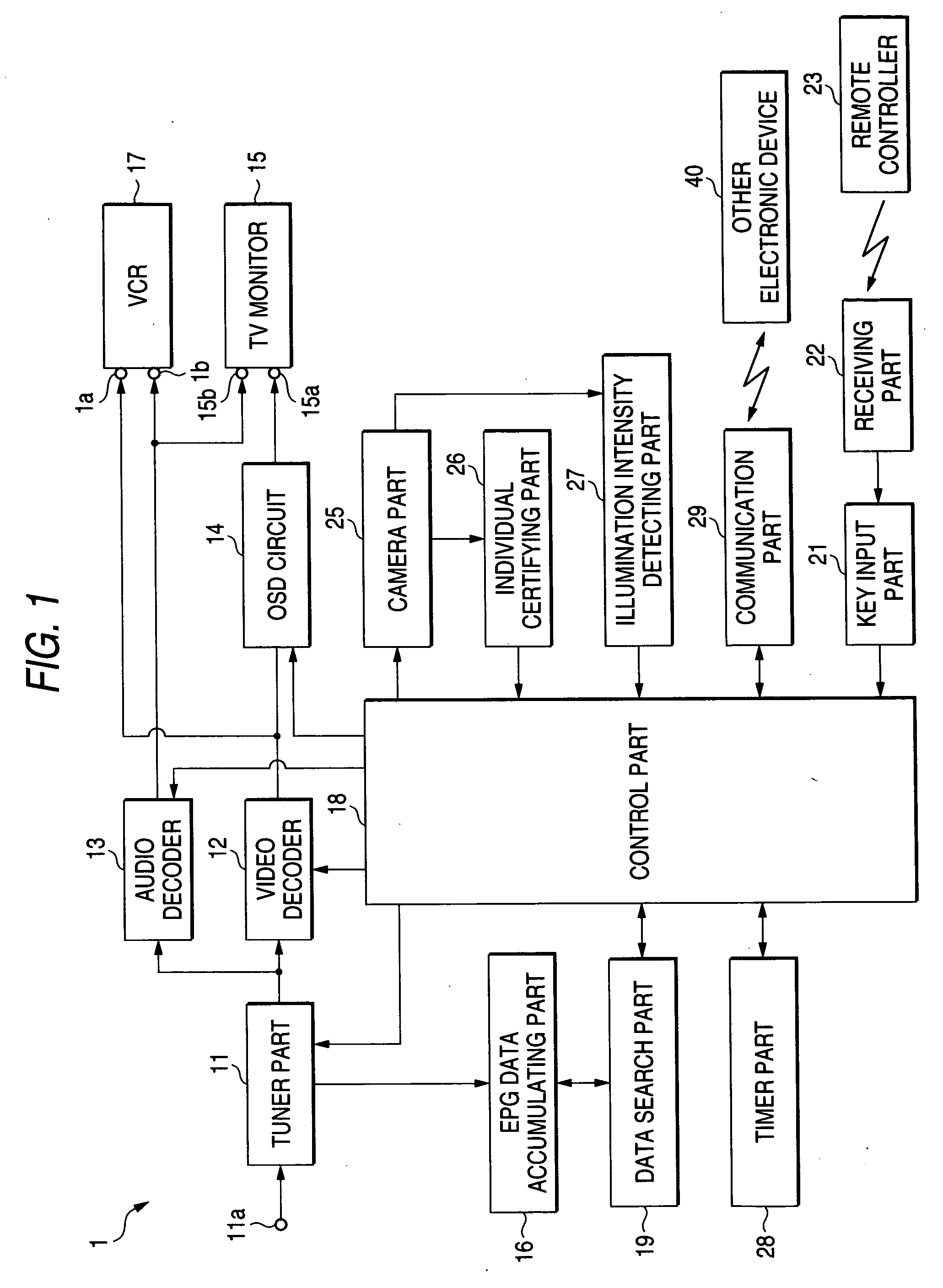
[0020]FIG. 1 is a functional block diagram showing the entire structure of a broadcasting signal receiving system of the present invention.

[0021] A broadcasting signal receiving system 1 includes an input terminal 11a for inputting a broadcasting signal received by an antenna not shown in the drawing and a tuner part 11 is connected to the input terminal 11a. An output of the tuner part 11 is connected to a video decoder 12 for converting a digital video signal to an analog video signal and connected to an audio decoder 13 for converting a digital audio signal to an analog audio signal. Further, the output of the vide decoder 12 is connected to a video input and output terminal 1a of a VCR (video cassette recorder) 17 and to a video input terminal 15a of a TV monitor 15 through an OSD (on screen display) circuit 14. Further, the output of the audio decoder 13 is connected to an audio ...


PUM


Abstract

A broadcasting signal receiving system includes: an obtaining part for obtaining program information of a receiving program; a broadcasting signal receiving part for receiving a broadcasting signal to obtain a video signal and an audio signal or a recorded image reproducing part for reproducing a previously recorded program to obtain a video signal and an audio signal; an image pick-up part for recording an image of a viewer; a certifying part for comparing the image with the previously registered image of a face of an individual to certify the viewing individual; an illumination intensity detecting part for detecting the brightness of a viewing space; and a viewing improvement control part for controlling the improvement of viewing on the basis of the certified result by the certifying part, a kind of the receiving program and the illumination intensity of the viewing space.

Description

BACKGROUND OF THE INVENTION [0001] 1. Field of the Invention [0002] The present invention relates to a broadcasting signal receiving system, and more particularly to a broadcasting signal receiving system on which a protecting function is installed for preventing a hyper-sensitivity to light that is apt to occur in such a case that infants view an animation program in a dark place. [0003] 2. Description of the Related Art [0004] Usually, a technique that information such as a video or an audio and a character is broadcast or distributed by an analog system or a digital system has been provided and a device for receiving these information and having various functions added has been proposed (for instance, see JP-A-2001-333030 and JP-A-2001-16514). [0005] The JP-A-2001-333030 discloses a broadcasting program transmitting and receiving system for controlling peripheral devices such as an air conditioner or an illuminating device in accordance with the contents of a broadcasting program...

Claims


Application Information

Patent Timeline
Patent Type & Authority Applications(United States)
IPC IPC(8): H04N7/16H04N5/44H04N5/445H04N5/60H05B37/02
CPCH04N5/58H04N7/163H04N21/4131H04N21/42202H04N21/84H04N21/4415H04N21/44218H04N21/4532H04N21/454H04N21/4223
Inventor MASAKI, YASUOSAWANAKA, TOMOHIKO
Owner FUNAI ELECTRIC CO LTD
Why Eureka
Try Eureka