Mobile station, fixed station, and radio communication system

a mobile station and radio communication technology, applied in the field of radio communication system, can solve the problems of mobile stations which do not contribute to data transmission, and require a lot of time to switch between modes, so as to avoid wasteful consumption of uplink radio resources

Inactive Publication Date: 2010-09-02
MITSUBISHI ELECTRIC CORP
View PDF16 Cites 25 Cited by
  • Summary
  • Abstract
  • Description
  • Claims
  • Application Information

AI Technical Summary

Benefits of technology

[0032]As a result, in a case in which no channel exclusively used for packet is transmitted, because the channel for transmit power control can be prevented from being transmitted, the present invention offers an advantage of being able to avoid wasteful consumption of the uplink radio resources.

Problems solved by technology

Because packets for data transmission have the property of being transmitted and received burstily, when there are many mobile stations which do not transmit and receive any data, regular DPCCH transmission and periodic CQI from such a mobile station causes consumption of the uplink radio resources.
However, the switching has the drawback of requiring much time to switch between the modes.
Because the conventional radio communications systems are constructed as mentioned above, a problem with the conventional radio communications systems is that when transmitting data by using only a channel exclusively used for packet, if there exists a physical control channel which is transmitted continuously, a mobile station which does not contribute to the data transmission consumes the uplink radio resources wastefully.
Although above-mentioned nonpatent reference 1 and patent references 1 and 2 disclose the methods of reducing the consumption of the uplink radio resources, they do not disclose any detailed operation specifications, any implementation methods, and so on, and therefore the wasteful consumption of the uplink radio resources cannot be avoided actually.
In a W-CDMA communications system, when no uplink DPDCH is transmitted (when any uplink DPDCH is not set up, or when any setting of an uplink DPDCH cannot be made as the capability of the mobile station), because dummy data need to be transmitted in order to carry out continuous transmission while it is not necessary to transmit control information for DPDCH by using a DPCCH, the radio resources are consumed wastefully.

Method used


Image

  • Mobile station, fixed station, and radio communication system
  • Mobile station, fixed station, and radio communication system
  • Mobile station, fixed station, and radio communication system

Examples


embodiment 1

[0053]In accordance with this Embodiment 1, a transmission control method of controlling transmission of a control channel is defined in detail according to a transmission status (a state or a mode) of a channel for packet transmission. As a result, the operations of mobile stations are unified.

[0054]In a communications system which uses a W-CDMA method, when transmission and reception of data are carried out using channels exclusively used for packet (used for HSDPA and for E-DCH), and conventional channels (a DCH and a DPDCH) are not transmitted as a real transmission time (or a transmission channel setting) or the transmission capacity of a mobile station, transmit power control is performed on an uplink control channel (particularly, a control channel DPCCH) in a physical layer.

[0055]Furthermore, the DPCCH is multiplied by a coefficient for channel transmit power control before the DPCCH is multiplexed with another channel.

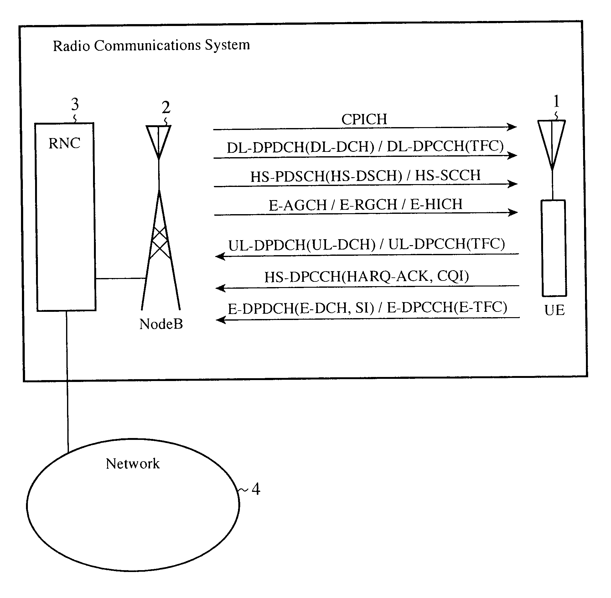
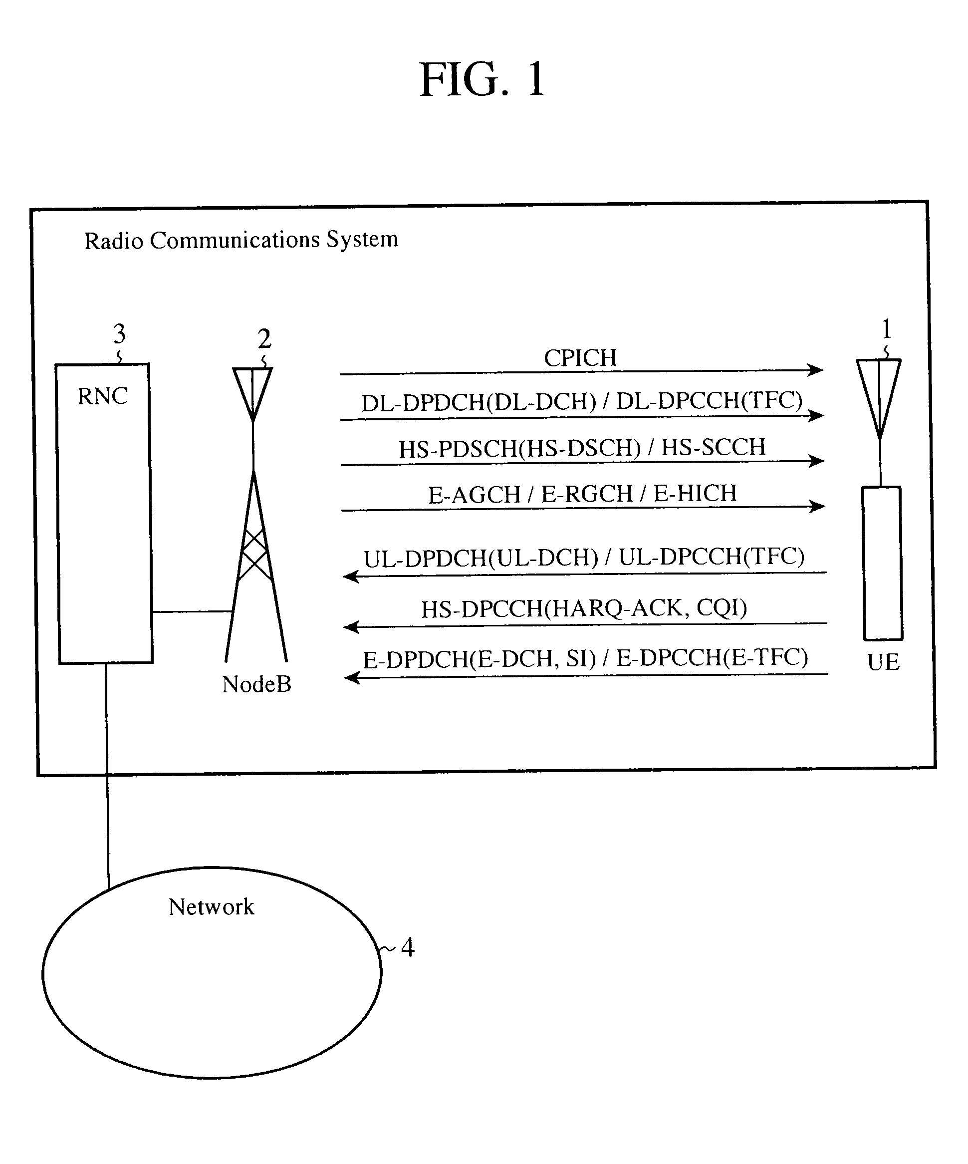
[0056]FIG. 1 is a block diagram showing a radio communic...

embodiment 2

[0269]In accordance with above-mentioned Embodiment 1, before a DPCCH is multiplexed with other uplink channels, the DPCCH is independently multiplied by the coefficients Cc and βc for transmit power control, as previously explained. In contrast, in accordance with this Embodiment 2, intervals at which a channel for transmit power control used for control of transmit power is to be transmitted is controlled according to the transmission status of a channel exclusively used for packet currently monitored by a transmission and reception channel monitoring unit 41, as will be explained below.

[0270]More specifically, in accordance with this Embodiment 2, a mobile station 1 which can discontinuously transmit an uplink DPCCH (UL-DPCCH), which, in a conventional art, can be transmitted continuously according to the transmission status of a channel exclusively used for packet, decreases or increases the degree (cycle) of the discontinuous transmission when switching between the continuous t...

embodiment 3

[0287]In above-mentioned Embodiment 2, the transmission intervals at which a channel for transmit power control used for control of the transmit power is to be transmitted are controlled according to the transmission (or reception) status of a channel exclusively used for packet currently monitored by the transmission and reception channel monitoring unit 41, as previously mentioned.

[0288]In contrast, in accordance with this Embodiment 3, in consideration of a transmit power set value for the channel for transmit power control for which a transmission mode is set up by a UL-DPCCH processing unit 32, a transmit power margin value of the channel exclusively used for packet is calculated, and the channel for transmit power control and the channel exclusively used for packet which is transmitted within the limits of the transmit power margin value are multiplexed.

[0289]More specifically, in accordance with this Embodiment 3, a case in which data transmission rate information about a cha...


PUM


Abstract

A UL-DPCCH processing unit sets up a transmission mode of a channel for transmit power control according to a transmission (or reception) status of a channel exclusively used for a packet, which is monitored by a transmission and reception channel monitoring unit, and the channel for transmit power control is multiplied by a channel coefficient corresponding to the transmission mode set up by the UL-DPCCH processing unit, and the channel for transmit power control multiplied by the channel coefficient and the channel exclusively used for packet are then multiplexed.

Description

FIELD OF THE INVENTION[0001]The present invention relates to a radio communications system comprised of a mobile station, such as a mobile phone, and a fixed station (a base station and a base station control apparatus). More particularly, it relates to a radio communications system comprised of a mobile station and a fixed station for which a channel via which packet data are transmitted is set up.BACKGROUND OF THE INVENTION[0002]Conventional radio communications systems have been developed assuming continuous and circuit switching data transmission services, such as voice calls.[0003]In recent years, discontinuous and packet switching data transmission services, such as Internet services, have been increasing.[0004]With this increase, an extension of specifications which is aimed at application to discontinuous and packet switching data communications has also been made for radio communications systems.[0005]For example, in W-CDMA communication methods which are called third gener...

Claims


Application Information

Patent Timeline
Patent Type & Authority Applications(United States)
IPC IPC(8): H04L12/26H04B1/707H04J13/00
CPCH04W24/00H04W88/02H04W76/02H04W52/54H04W76/10
Inventor NIWANO, KAZUHITO
Owner MITSUBISHI ELECTRIC CORP
Why Eureka
Try Eureka