
Image forming apparatus

a technology of forming apparatus and forming device, which is applied in the direction of electrographic process apparatus, instruments, optics, etc., can solve the problems of wasteful energy consumption inability to achieve correct feedback control, and waste of laser source power during irradiation of laser light, so as to prevent waste of energy and avoid waste of energy. , the effect of reducing the number of fixing devices

Active Publication Date: 2012-09-20
SHARP KK
View PDF3 Cites 4 Cited by
  • Summary
  • Abstract
  • Description
  • Claims
  • Application Information

AI Technical Summary

Benefits of technology

[0010]The present invention has been devised in view of the above circumstances, it is therefore and object of the present invention to provide an image forming apparatus in which multiple number of laser beams are controlled to perform fixing based on the toner concentration in the developing device, or based on the density and weight of the toner image adhering on the recording medium before fixing, to thereby efficiently use the energy for irradiation of laser light for fixing.

Problems solved by technology

However, since the toner is thermally fused instantly by the laser light, the temperature detected by the temperature detector is not the actual temperature of the toner during its being heated.
As a result, this method cannot achieve correct feedback control and entails the problem that the power of the laser source during irradiation of laser light is consumed wastefully.
In the fixing device of patent document 2, the energy for irradiation of laser light is used without taking into account any factor of the unfixed toner adhering on the recording medium before fixing, so that there is the problem that waste energy is consumed when the toner is irradiated with laser light.

Method used


Image

  • Image forming apparatus
  • Image forming apparatus
  • Image forming apparatus

Examples


first embodiment

The First Embodiment

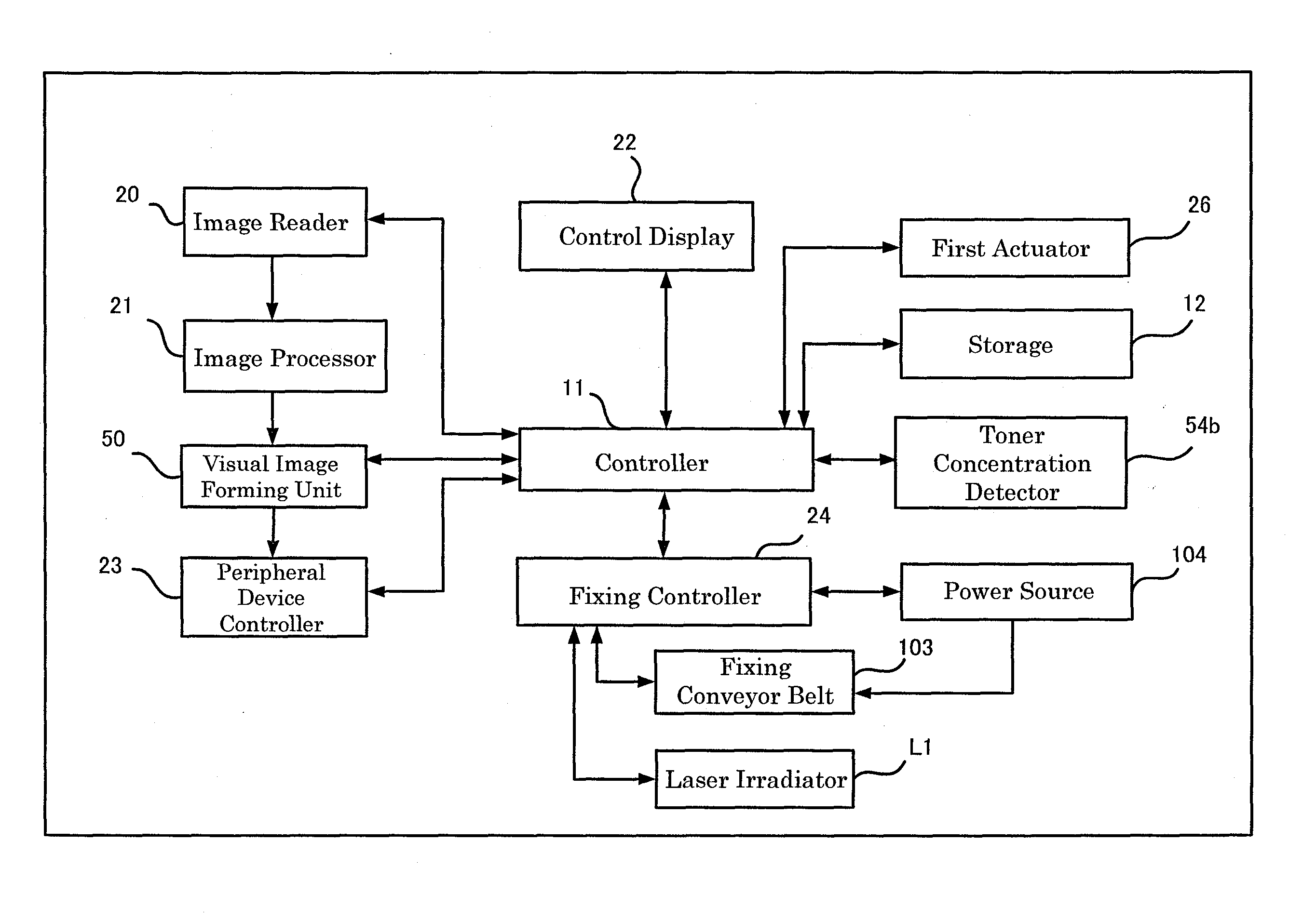
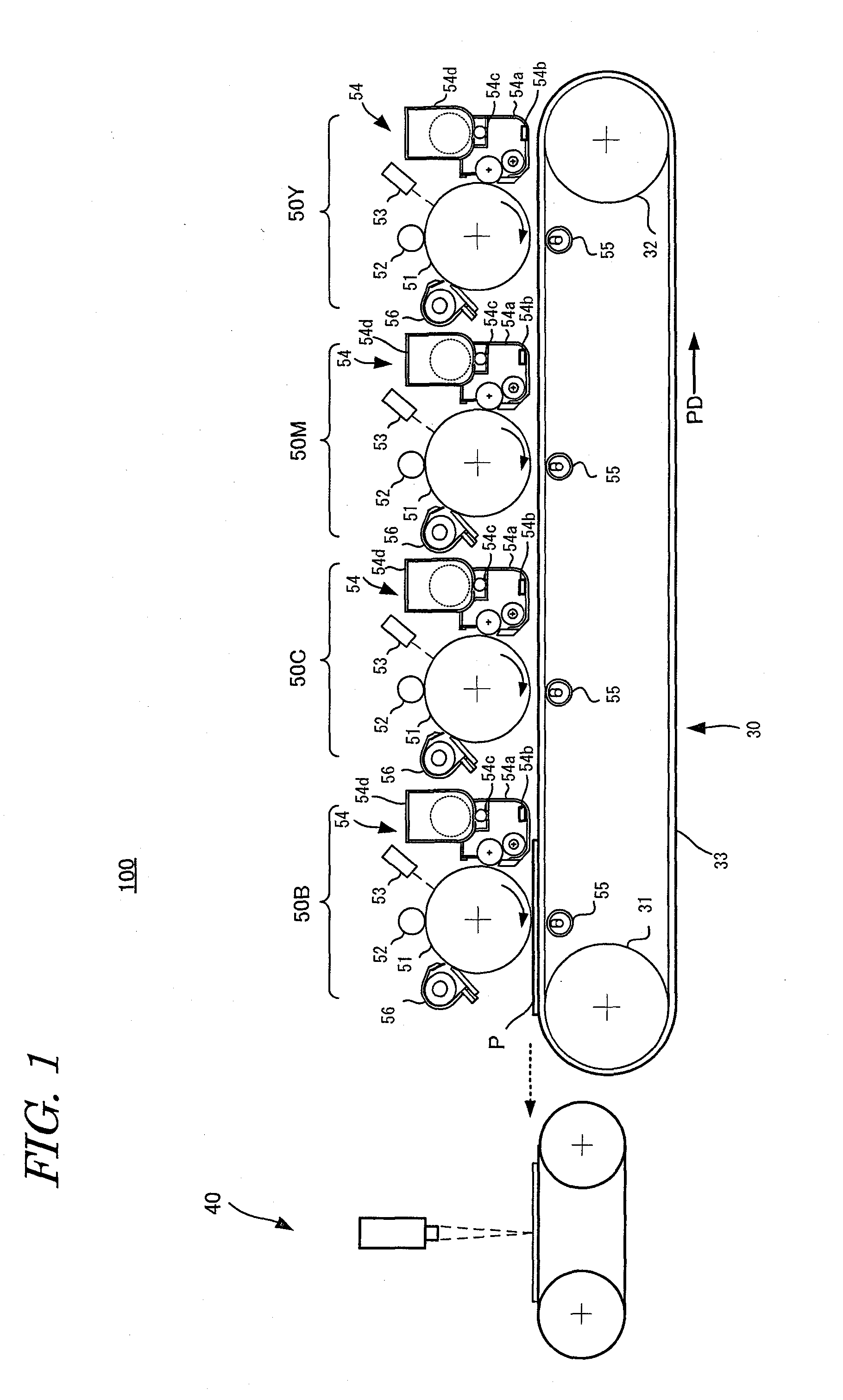
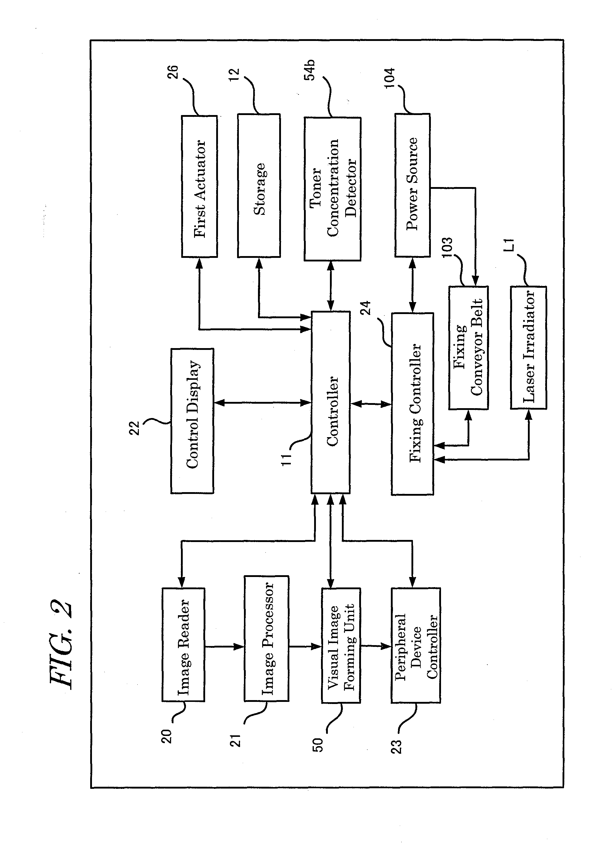
[0045]Next, an image forming apparatus 100 including a fixing device 40 according to the first embodiment of the present invention will be described. In the first embodiment, the image forming apparatus is applied to a color multifunctional machine. FIG. 1 is a schematic diagram showing a configuration of image forming apparatus 100 including fixing device 40 according to the first embodiment.

[0046]Since amono-component development system is not suitable for high-speed development though the system is preferable for miniaturization, a developing device 54 of a type using a dual-component developer is used in the first embodiment.

[0047]The carrier itself in the dual-component developer is not consumed but remains inside the developer without reduction, whereas the toner is used and reduced by developing operation. For this reason, in order to prevent instability of image quality due to decrease of the toner forming the dual-component developer, toner concentration...

second embodiment

The Second Embodiment

[0133]Next, an image forming apparatus 101 according to the second embodiment of the present invention will be detailed with reference to FIG. 15. FIG. 15 is a schematic diagram of image forming apparatus 101 according to the second embodiment of the present invention. Since the components in image forming apparatus 101 of the second embodiment are the same as those of the first embodiment except for a weight measuring unit 41, description of the components other than weight measuring unit 41 is omitted.

[0134]Now, fixing control of fixing device 40 of image forming apparatus 101 including weight measuring unit 41 will be described. Instead of toner concentration detector 54b according to the first embodiment, fixing control based on weight measuring unit 41 is performed in the second embodiment.

[0135]Even if an unfixed toner image is formed based on identical positional information on printing, the toner density and the amount of adherence (weight of the unfixed...


PUM


Abstract

To provide an image forming apparatus in which multiple number of laser beams are controlled to perform fixing based on the toner concentration in the developing device, or based on the density and weight of the toner image adhering on the recording medium before fixing. The controller in the image forming apparatus compares the toner concentration detected by the toner concentration detector with the reference toner concentration, calculates the output level of the laser irradiator, controls the laser irradiator based on the calculation, controls to increase the output level of the laser irradiator in accordance with the detected toner concentration when the toner concentration is lower than the reference toner concentration, and controls to lower the output level of the laser irradiator in accordance with the detected toner concentration when the toner concentration is higher than the reference toner concentration.

Description

[0001]This Non provisional application claims priority under 35 U.S.C. §119 (a) on Patent Application No. 2011-058136 filed in Japan on 16 Mar. 2011, the entire contents of which are hereby incorporated by reference.BACKGROUND OF THE INVENTION[0002](1) Field of the Invention[0003]The present invention relates to an image forming apparatus based on electrophotography, such as a copier, printer, facsimile machine or the like, more detailedly relating to an image forming apparatus which supplies toner to a static latent image formed on a photoreceptor drum, transfers a developed toner image to a recording medium and fuses the unfixed toner image by irradiation of laser light to fix the toner image to the recording medium.[0004](2) Description of the Prior Art[0005]Image forming apparatuses (e.g., printers and the like) using the electrophotographic technique, include a fixing device that fix the toner image formed on the recording medium (paper) to the paper by thermally fusing the ton...

Claims


Application Information

Patent Timeline
Patent Type & Authority Applications(United States)
IPC IPC(8): G03G15/20
CPCG03G15/0189G03G2215/0132G03G15/5062
Inventor MAEDA, TOMOHIRO
Owner SHARP KK
Learn More