Ion plating apparatus that prevents wasteful consumption of evaporation material

A technology of ion coating and plasma beam, applied in the field of ion coating device

Inactive Publication Date: 2004-05-26
SUMITOMO HEAVY IND LTD
View PDF0 Cites 0 Cited by
  • Summary
  • Abstract
  • Description
  • Claims
  • Application Information

AI Technical Summary

Problems solved by technology

Especially when using high-efficiency or high-p...

Method used


Image

  • Ion plating apparatus that prevents wasteful consumption of evaporation material
  • Ion plating apparatus that prevents wasteful consumption of evaporation material
  • Ion plating apparatus that prevents wasteful consumption of evaporation material

Examples


Embodiment Construction

[0012] The preferred embodiment of the present invention is described as follows:

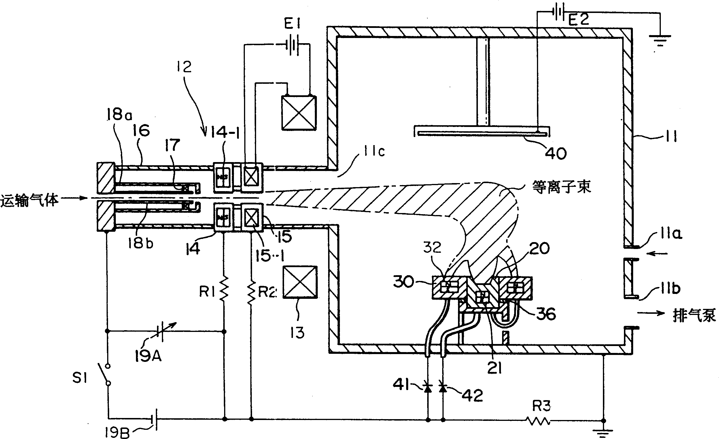
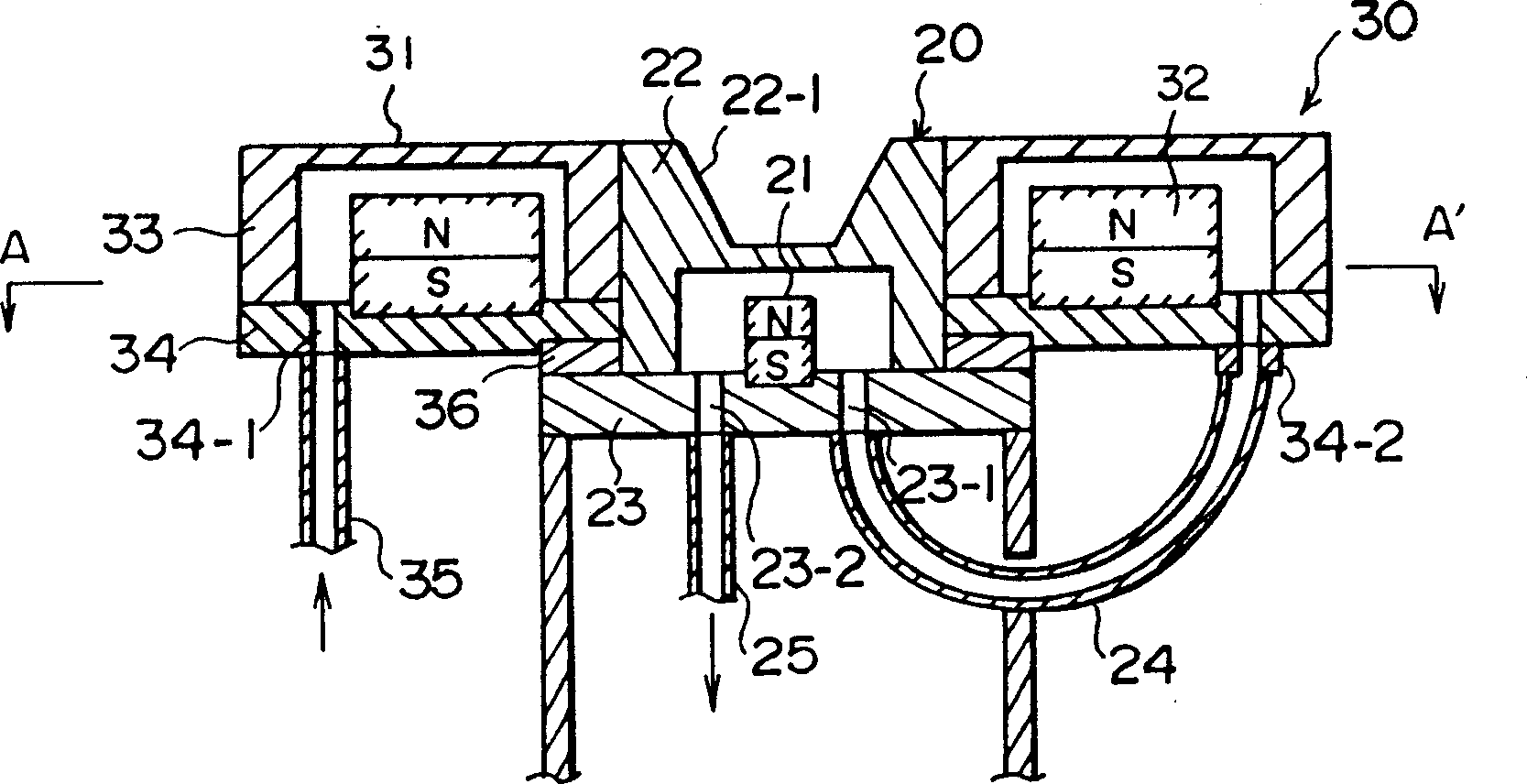
[0013] refer to figure 1 and figure 2 It is a conventional ion coating device shown in order to better understand the essence of the present invention.

[0014] exist figure 1 Among them, the ion coating device includes a vacuum chamber 11, and on the side wall of the vacuum chamber 11, there are an inlet 11a and an outlet 11b for leading in and out gases such as argon. The inlet 11a is connected to an air source (not shown), and the outlet 11b is connected to an exhaust pump (not shown). The side wall of the vacuum chamber 11 also has a hole 11c. The hole 11c houses a plasma beam generator 12 having a pressure gradient. Around the outer surface of the hole 11c is mounted a control coil 13 for guiding the plasma beam.

[0015] The plasma beam generator 12 has a first intermediate electrode 14 and a second intermediate electrode 15 for confining the plasma beam. The first and second inte...


PUM


Abstract

A plasma beam is directed towards a hearth to flow electric current of the plasma through the hearth during formation of a thin film on a substrate. The plasma beam is directed towards an auxiliary anode to flow electric current of the plasma through the auxiliary anode during the period after completion of the formation of the thin film on the substrate and before beginning of the formation of a thin film on the subsequent substrate.

Description

technical field [0001] The present invention relates to an ion coating device using plasma and an operating method suitable for the device. Background technique [0002] Typical known ion coating devices are a pressure gradient plasma source using arc discharge or an HCD plasma source. An ion coating device includes a plasma generator (plasma source). A plasma beam is generated between the plasma generator and the crucible (anode) located in the vacuum chamber. The plasma beam is extended to evaporate the evaporation material in the crucible. The metal particles evaporated from the evaporation material are ionized by the plasma beam. The ionized metal particles are deposited in a predetermined amount on the surface of the substrate opposite the crucible in the vacuum chamber. As a result, a thin film can be formed on the substrate. [0003] In a common ion coating device, the substrate can be transported throughout the process, that is, the substrate is transferred from...

Claims


Application Information

Patent Timeline
IPC IPC(8): C23C14/32H05H1/54
CPCH05H1/54C23C14/32C23C14/46
Inventor 酒见俊之田中胜
Owner SUMITOMO HEAVY IND LTD
Why Eureka
Try Eureka