Liquid discharging apparatus

a technology of liquid discharging apparatus and droplet, which is applied in the direction of printing apparatus, inking apparatus, other printing apparatus, etc., can solve the problems of poor landing of the droplet onto the target surface, the droplet discharging timing or the wrong amount deviating from the target value, and the droplet ejected from the nozzle in the air. , to achieve the effect of enhancing the reliability of discharging liquid, preventing liquid from stagnating, and reducing the risk o

Active Publication Date: 2018-12-06
SEIKO EPSON CORP
View PDF4 Cites 0 Cited by
  • Summary
  • Abstract
  • Description
  • Claims
  • Application Information

AI Technical Summary

Benefits of technology

[0009][4] The liquid discharging apparatus of the above aspect may further include: a flowing-out passage through which the liquid flows out from the liquid compartment. This preferred liquid discharging apparatus makes it possible to produce a flow of the liquid from the flowing-in passage toward the flowing-out passage in the liquid compartment, thereby preventing the liquid from stagnating inside the liquid compartment. Moreover, it is possible to cause air bubbles produced as a result of entry of external air into the liquid compartment to flow out through the flowing-out passage. Therefore, the risk of occurrence of poor discharging caused by the stagnation of the liquid inside the liquid compartment or by the presence of air bubbles inside the liquid compartment decreases, resulting in enhanced reliability in discharging the liquid.
[0010][5] The preferred liquid discharging apparatus may further include: a circulation passage for circulation, to the liquid compartment, of the liquid flowing out through the flowing-out passage. This preferred liquid discharging apparatus makes it possible to prevent the liquid from stagnating inside the liquid compartment by produce the flow of the liquid from the flowing-in passage toward the flowing-out passage in the liquid compartment and to avoid wasteful consumption of the liquid flowing out through the flowing-out passage.
[0011][6] The liquid discharging apparatus of the above aspect may further include: a controller that controls the capacity changer and the flowing-in passage resistance changer, and executes discharge processing for discharging the liquid in a form of a droplet from the nozzle, wherein, in the discharge processing, the controller may cause the liquid to start going out from the nozzle by causing the capacity changer to decrease the capacity of the liquid compartment, and cause the flowing-in passage resistance changer to increase the capacity of the flowing-in passage during the going out of the liquid from the nozzle so as to separate the droplet from the liquid of the nozzle and release the droplet into air. This preferred liquid discharging apparatus makes it possible to produce a suction force for sucking the liquid going out through the communication opening back toward the flowing-in opening by increasing the capacity of the flowing-in passage during the discharging of the liquid from the nozzle. The suction force facilitates the separation, from the liquid in the nozzle, of the liquid going out from the nozzle, and reduces the risk of occurrence of poor discharging caused by a phenomenon of wastefully forming a tail by the liquid discharged from the nozzle. Since it is possible to produce the force for discharging the liquid from the nozzle and the force for releasing the droplet from the nozzle by means of different drive units, that is, the capacity changer and the flowing-in passage resistance changer, resulting in enhanced controllability in the pressure change inside the liquid compartment in discharge processing.
[0012][7] In the preferred liquid discharging apparatus, in the discharge processing, before causing the capacity changer to decrease the capacity of the liquid compartment so as to cause the liquid to start going out from the nozzle, the controller may cause the flowing-in passage resistance changer to increase the flow resistance of the flowing-in passage. This preferred liquid discharging apparatus makes it possible to prevent the pressure produced due to the driving of the capacity changer for discharging the liquid from escaping into the flowing-in passage.
[0013][8] The preferred liquid discharging apparatus may further include: a flowing-out passage resistance changer that changes capacity of the flowing-out passage to change flow resistance of the flowing-in passage; and a controller that controls the capacity changer, the flowing-in passage resistance changer, and the flowing-out passage resistance changer, and executes discharge processing for discharging the liquid in a form of a droplet from the nozzle, wherein, in the discharge processing, the controller may cause the liquid to start going out from the nozzle by causing the capacity changer to decrease the capacity of the liquid compartment, and cause the flowing-in passage resistance changer to increase the capacity of the flowing-in passage during the going out of the liquid from the nozzle so as to separate the droplet from the liquid of the nozzle and release the droplet into air; and wherein, in the discharge processing, before causing the capacity changer to decrease the capacity of the liquid compartment so as to cause the liquid to start going out from the nozzle, the controller may cause the flowing-in passage resistance changer to increase the flow resistance of the flowing-in passage and causes the flowing-out passage resistance changer to increase the flow resistance of the flowing-out passage. This preferred liquid discharging apparatus makes it possible to produce, in discharge processing, the force for discharging the liquid from the nozzle and the force for releasing the droplet from the nozzle by means of different drive units, that is, the capacity changer and the flowing-in passage resistance changer. Therefore, controllability in the pressure change inside the liquid compartment in discharge processing enhances. Moreover, it is possible to prevent the pressure produced due to the driving of the capacity changer for discharging the liquid from escaping into the flowing-in passage and the flowing-out passage when the liquid is discharged from the nozzle.
[0014][9] In the preferred liquid discharging apparatus, the controller may cause the capacity changer to increase the capacity of the liquid compartment in a process of causing the flowing-in passage resistance changer to decrease the capacity of the flowing-in passage. This preferred liquid discharging apparatus makes it possible to prevent the liquid forced out due to the decrease in the capacity of the flowing-in passage from leaking out from the nozzle before the start of discharging of the liquid from the nozzle. Therefore, poor discharging of the liquid due to unwanted leakage of the liquid from the nozzle is suppressed.

Problems solved by technology

There is a possibility of wrong droplet discharging timing or wrong discharge amount deviated from the target value if the timing of changing the pressure inside the liquid compartment deviates from the target.
Moreover, there is a possibility of generation of unwanted mist, resulting in poor traveling of the droplet ejected from the nozzle into the air and poor landing of the droplet onto a target surface.
However, in general, there is a limit in the response speed and operation speed of an actuator configured to change the pressure inside a liquid compartment.
The problem described above applies not only to a liquid discharging apparatus using a piezoelectric element as an actuator for changing the pressure inside a liquid compartment but also to a liquid discharging apparatus using other kind of actuator for changing the pressure inside a liquid compartment.

Method used


Image

  • Liquid discharging apparatus
  • Liquid discharging apparatus
  • Liquid discharging apparatus

Examples


first embodiment

A. First Embodiment

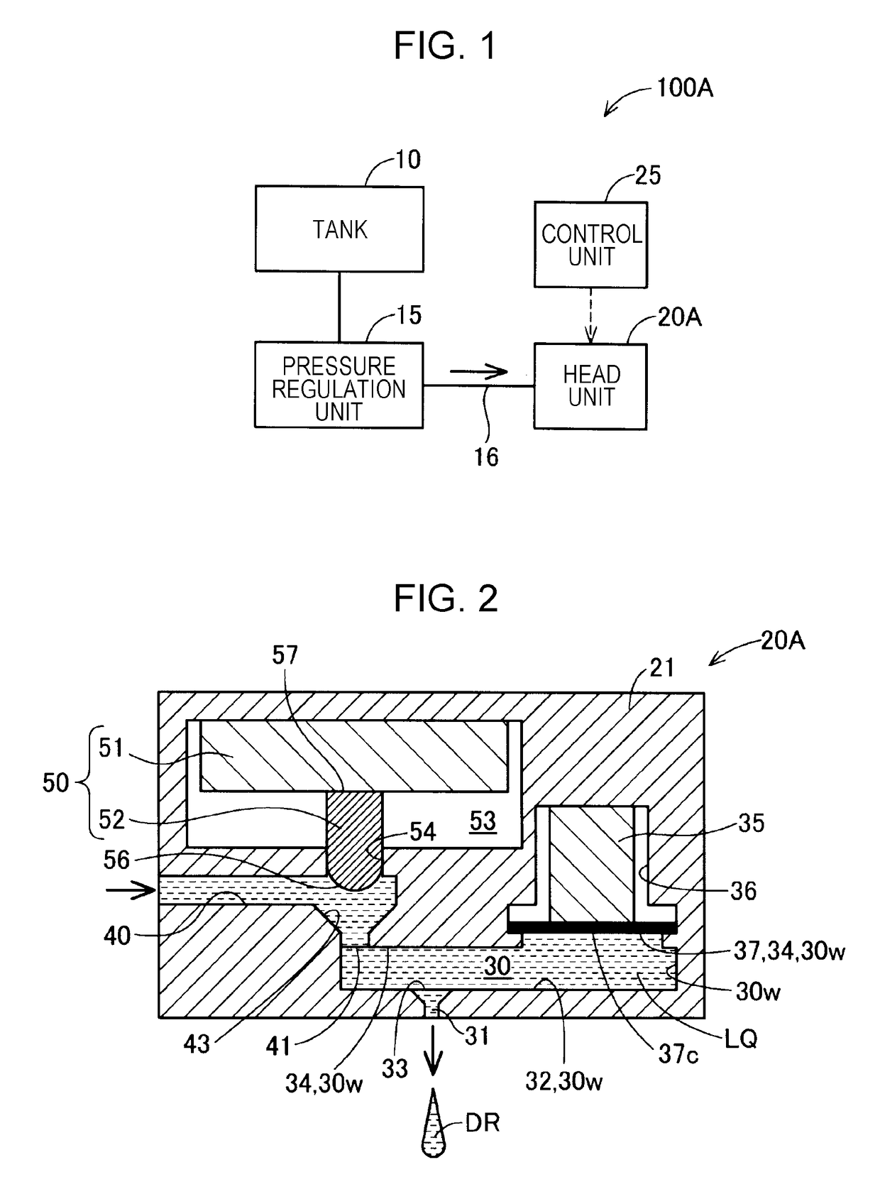
[0029]FIG. 1 is a schematic block diagram that illustrates the overall configuration of a liquid discharging apparatus 100A according to a first embodiment. The liquid discharging apparatus 100A includes a tank 10, a pressure regulation unit 15, a supply passage 16, a head unit 20A, and a control unit 25.

[0030]A liquid is contained in the tank 10. The liquid is, for example, ink that has predetermined viscosity. The liquid contained in the tank 10 is supplied to the head unit 20A through the supply passage 16, which is connected to the head unit 20A.

[0031]The pressure regulation unit 15 is provided on the supply passage 16. The pressure regulation unit 15 adjusts the pressure of the liquid supplied to the head unit 20A through the supply passage 16 into predetermined pressure. The pressure regulation unit 15 is, for example, a pump for sucking the liquid out of the tank 10, or a valve that opens and closes so as to adjust pressure at the side where the head unit 2...

second embodiment

B. Second Embodiment

[0066]FIG. 5 is a schematic sectional view of the internal structure of a head unit 20B of a liquid discharging apparatus 100B according to a second embodiment. The structure of the liquid discharging apparatus 100B according to the second embodiment is substantially the same as that of the liquid discharging apparatus 100A according to the first embodiment (FIG. 1), except that the head unit 20A according to the first embodiment is replaced with the head unit 20B according to the second embodiment. The structure of the head unit 20B according to the second embodiment is substantially the same as that of the head unit 20A according to the first embodiment (FIG. 2), except that, in the liquid compartment 30, the position where the nozzle 31 is formed and where its communication opening 33 is formed is different from the position in the first embodiment. In the liquid discharging apparatus 100B according to the second embodiment, the control unit 25 performs discha...

third embodiment

C. Third Embodiment

[0068]FIG. 6 is a schematic block diagram that illustrates the overall configuration of a liquid discharging apparatus 100C according to a third embodiment. The structure of the liquid discharging apparatus 100C according to the third embodiment is substantially the same as that of the liquid discharging apparatus 100A according to the first embodiment (FIG. 1), except for the points of difference explained below. The liquid discharging apparatus 100C includes a pressurizing pump 60 in place of the pressure regulation unit 15, and includes a head unit 20C according to the third embodiment in place of the head unit 20A according to the first embodiment. Moreover, the liquid discharging apparatus 100C includes a drain passage 61, a liquid reservoir 63, a negative pressure generation source 64, and a circulation passage 65 additionally.

[0069]The pressurizing pump 60 operates to supply the liquid contained in the tank 10 to the head unit 20C through the supply passage...


PUM


Abstract

A liquid discharging apparatus includes: a liquid compartment; a flowing-in passage that is in communication with the liquid compartment through a flowing-in opening, the liquid flowing through the flowing-in passage into the liquid compartment; a nozzle that is in communication with the liquid compartment through a communication opening; a capacity changer that causes the liquid contained in the liquid compartment to be discharged from the nozzle by causing a displacement of an inner wall surface of the liquid component and changing capacity of the liquid compartment; and a flowing-in passage resistance changer that changes capacity of the flowing-in passage to change flow resistance of the flowing-in passage. In the liquid compartment, as viewed from the flowing-in opening, the communication opening is located in front of a center-of-displacement portion, an amount of the displacement of which is largest in the inner wall surface displaced by the capacity changer.

Description

BACKGROUND1. Technical Field[0001]The present invention relates to a liquid discharging apparatus.2. Related Art[0002]Various kinds of the following liquid discharging apparatus have been proposed in related art, for example, as disclosed in JP-A-2010-274446; the apparatus is configured to discharge a liquid contained in a liquid compartment from a nozzle that is in communication with the liquid compartment by changing the capacity of the liquid compartment using an actuator and by changing the pressure inside the liquid compartment.[0003]In the liquid discharging apparatus mentioned above, preferably, the pressure inside the liquid compartment should be changed appropriately at ideal target timing for the purpose of controlling the discharging of the liquid from the nozzle with higher precision. There is a possibility of wrong droplet discharging timing or wrong discharge amount deviated from the target value if the timing of changing the pressure inside the liquid compartment devi...

Claims


Application Information

Patent Timeline
Patent Type & Authority Applications(United States)
IPC IPC(8): B41J2/045B41J29/38
CPCB41J2/04581B41J29/38B41J2/04541B41J2/07B41J2/14201B41J2/175B41J2/18B41J2/14274B41J2202/05
Inventor SAKAI, HIROFUMIKATAKURA, TAKAHIROSUGAI, KEIGONAKAMURA, SHINICHISANO, JUNICHI
Owner SEIKO EPSON CORP
Why Eureka
Try Eureka