Rolling Bearing Apparatus

a technology of rolling bearings and rollers, which is applied in the direction of bearing components, shafts, shafts, etc., can solve the problems of limited capacity of the tank, and increased unexpected consumption of lubricant, so as to reduce wasteful consumption of lubrican

Inactive Publication Date: 2017-11-16
JTEKT CORP
View PDF3 Cites 2 Cited by
  • Summary
  • Abstract
  • Description
  • Claims
  • Application Information

AI Technical Summary

Benefits of technology

[0009]When the bearing rotates, the air in an annular space between the inner ring and the outer ring also rotates. However, due to the wind guard, the oil droplet emitted from the pump can easily reach the target of the bearing. Further, a negative pressure is caused in the opening of the wind guard on the target side by the air thus rotating; the inner region of the wind guard has a passage shape causing the airflow from the nozzle side toward the opening on the target side. This causes an action to carry the lubricant floating around the nozzle to the opening of the wind guard on the target side. As a result, it is possible to eventually supply the lubricant carried to the opening to the bearing on the flow of the air rotating in the annular space, thereby making it possible to restrain wasteful consumption of the lubricant.
[0010]In order to cause the airflow in the inner region of the wind guard, a pressure (an atmospheric pressure) on the nozzle side should be made higher than a pressure of the opening on the target side in the inner region. In view of this, a nozzle-side part of the wind guard may be provided with an intake port allowing an air to be taken into the inner region including the passing region from an outer region of the wind guard. Hereby, the pressure (the atmospheric pressure) on the nozzle side can be made higher than the pressure of the opening on the target side in the inner region of the wind guard, so that the airflow like the above can be generated. Further, the passage shape of the inner region may be formed such that a passage cross-section on the nozzle side is larger than a passage cross-section on the opening side. Hereby, the pressure (the atmospheric pressure) on the nozzle side can be made higher than the pressure of the opening on the target side in the inner region of the wind guard, so that the airflow like the above can be generated.
[0011]Further, the inner region may have a passage portion on the opening side, a passage portion on the nozzle side with a passage cross-section larger than that on the opening side, and a large-diameter portion having a passage cross-section suddenly expanding from the passage portion on the nozzle side and opposed to a body wall portion of the pump where the nozzle is opened. With this configuration, in the inner region of the wind guard, the pressure (the atmospheric pressure) on the nozzle side can be made higher than the pressure of the opening on the target side, so that the airflow like the above can be generated. Further, it is possible to cause an action to carry the lubricant floating around the nozzle from a wide area to the opening of the wind guard on the target side by the large-diameter portion.
[0012]According to the aspect of the present disclosure, it is possible to restrain wasteful consumption of the lubricant and to cause the oil supply unit to function for a long period.

Problems solved by technology

When the main spindle rotates at a high speed, a lubricating ability in particular becomes a problem in terms of a bearing that supports the main spindle.
In such a rolling bearing apparatus, the tank into which the lubricant is accumulated and the bearing are provided in a small annular space between a spindle and a housing, so the capacity of the tank is limited.
Since an oil amount of the satellite is large relative to an oil amount of the main oil droplet, the lubricant consumed by the tank increases unexpectedly.
Further, the satellite following the main oil droplet should reach the target of the bearing, but the satellite may delay from the main oil droplet so as to float around a nozzle of the pump or may be attached to a wall surface of the pump where the nozzle is opened, so that the satellite can be hardly used for lubrication of the bearing.
That is, the conventional oil supply unit has a problem that the lubricant may be consumed in vain.
However, due to the wind guard, the oil droplet emitted from the pump can easily reach the target of the bearing.

Method used


Image

  • Rolling Bearing Apparatus
  • Rolling Bearing Apparatus
  • Rolling Bearing Apparatus

Examples


Embodiment Construction

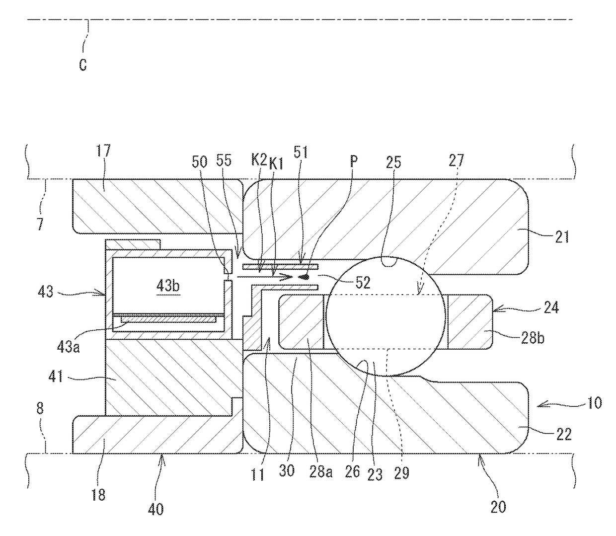
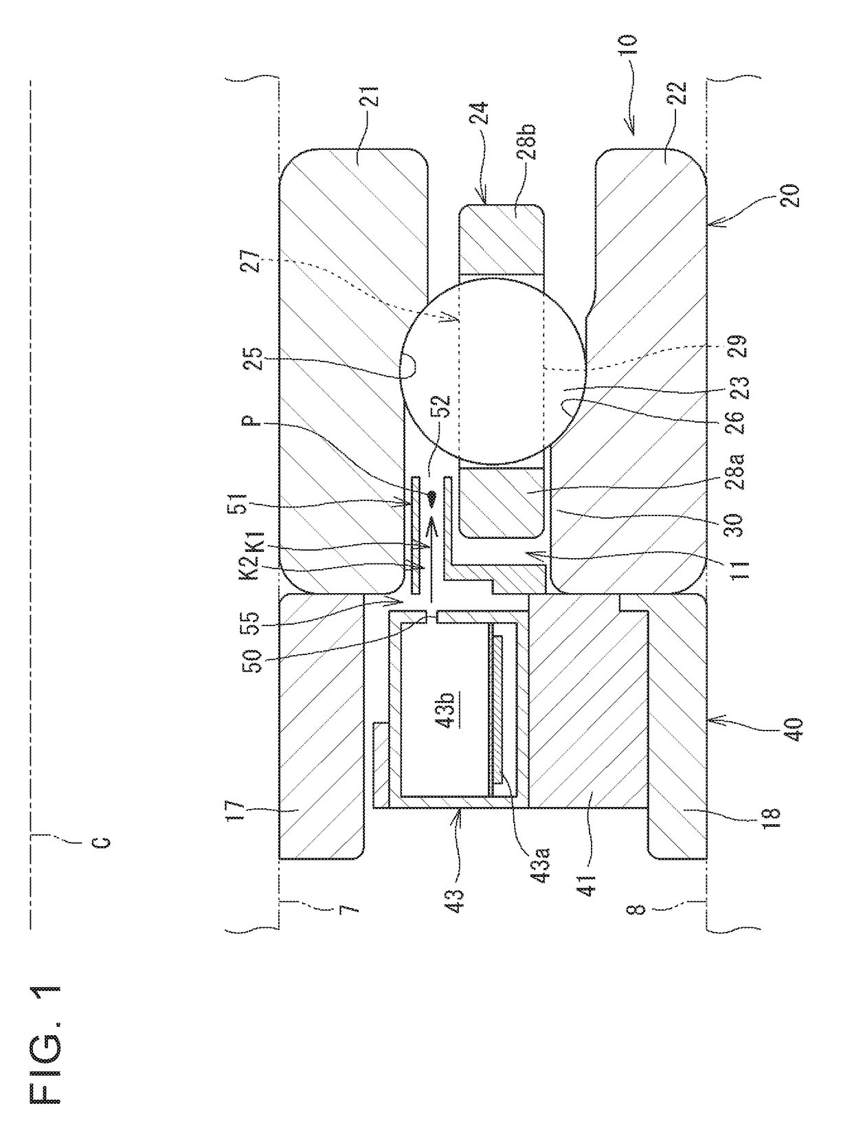
[0021]The following describes one embodiment of a rolling bearing apparatus of the disclosure. FIG. 1 is a sectional view illustrating one embodiment of the rolling bearing apparatus. The rolling bearing apparatus 10 (hereinafter also referred to as the bearing apparatus 10) illustrated in FIG. 1 rotatably supports a main spindle (a spindle 7) of a main spindle device included in a machine tool and is accommodated in a bearing housing 8 of the main spindle device. In FIG. 1, the spindle 7 and the bearing housing 8 are indicated by an alternate long and two short dashes line. Note that the bearing apparatus 10 is also applicable to a device other than the machine tool. Further, in the following description, a direction parallel to a center line C of the bearing apparatus 10 is referred to as an axial direction and a direction perpendicular to the axial direction is referred to as a radial direction.

[0022]The bearing apparatus 10 includes a bearing 20 and an oil supply unit 40. The be...


PUM

PropertyMeasurementUnit
pressureaaaaaaaaaa
diameteraaaaaaaaaa
speedaaaaaaaaaa

Abstract

A rolling bearing apparatus includes: a bearing including an inner ring, an outer ring, a plurality of rolling elements, and a cage; and an oil supply unit provided axially adjacent to the bearing. The oil supply unit includes: a tank in which to accumulate lubricant; and a pump provided with a nozzle that emits the lubricant as an oil droplet toward a target of the bearing. The oil supply unit further includes a wind guard covering a passing region of the oil droplet thus emitted from the nozzle and having an opening toward a target side. An inner region of the wind guard, including the passing region, has a passage shape causing an airflow from a nozzle-side toward the opening on the target side where a negative pressure is caused due to a bearing rotation.

Description

INCORPORATION BY REFERENCE[0001]The disclosure of Japanese Patent Application No. 2016-095283 filed on May 11, 2016 including the specification, drawings and abstract is incorporated herein by reference in its entirety.BACKGROUND1. Technical Field[0002]The present disclosure relates to a rolling bearing apparatus including a bearing, and an oil supply unit provided axially adjacent to the bearing.2. Description of Related Art[0003]In recent years, speedup of a main spindle has been requested to various machine tools for improvement of machining efficiency and production efficiency. When the main spindle rotates at a high speed, a lubricating ability in particular becomes a problem in terms of a bearing that supports the main spindle. In view of this, there has been proposed a rolling bearing apparatus provided in an oil supply unit axially adjacent to the bearing (see Japanese Patent Application Publication No. 2004-108388 (JP 2004-108388 A)). The oil supply unit includes a tank int...

Claims


Application Information

Patent Timeline
Patent Type & Authority Applications(United States)
IPC IPC(8): F16C33/66F16C19/06
CPCF16C33/6659F16C19/06F16C2322/39F16C33/664F16C33/6674F16C33/38F16C33/6637
Inventor TANIMOTO, KIYOSHI
Owner JTEKT CORP
Why Eureka
Try Eureka