Methods and Apparatus for Prepaid Card Packaging

a technology of prepaid cards and packaging methods, applied in the field of prepaid card packaging and activation, can solve the problems of not providing the right balance of features, too expensive, and the packaging of highly secure cards may be too susceptible to fraud,

Active Publication Date: 2010-09-09
IDEMIA AMERICA CORP
View PDF10 Cites 43 Cited by
  • Summary
  • Abstract
  • Description
  • Claims
  • Application Information

AI Technical Summary

Problems solved by technology

While a wide variety of previous approaches have been tried, many such approaches have failed to provide the right balance of features.
For example, a highly secure package may be too hard to open by a legitimate customer after purchase, too expensive or both.
A very cost effective package may be too susceptible to fraud.
Where the bar code is externally on the card packaging it is publicly accessible and potentially subject to attack.
In such an approach, the bar code is again publicly visible and accessible and is potentially subject to fraud attempts.

Method used


Image

  • Methods and Apparatus for Prepaid Card Packaging
  • Methods and Apparatus for Prepaid Card Packaging
  • Methods and Apparatus for Prepaid Card Packaging

Examples


first embodiment

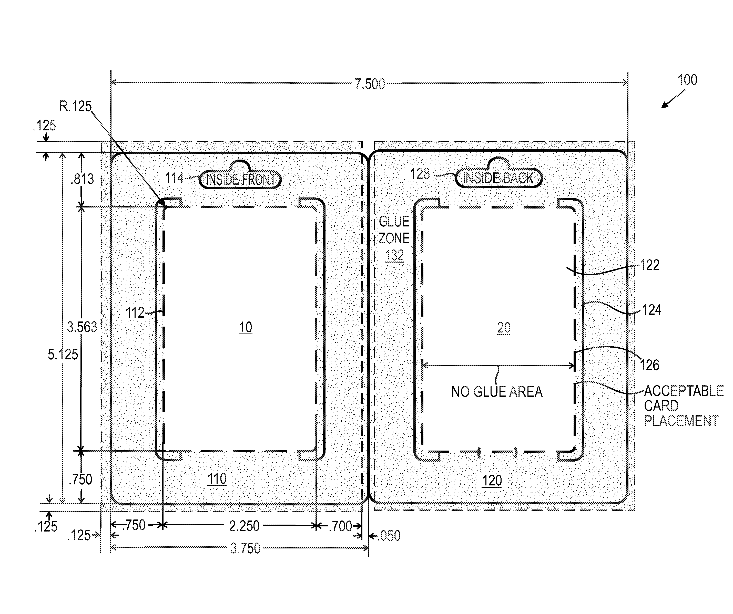
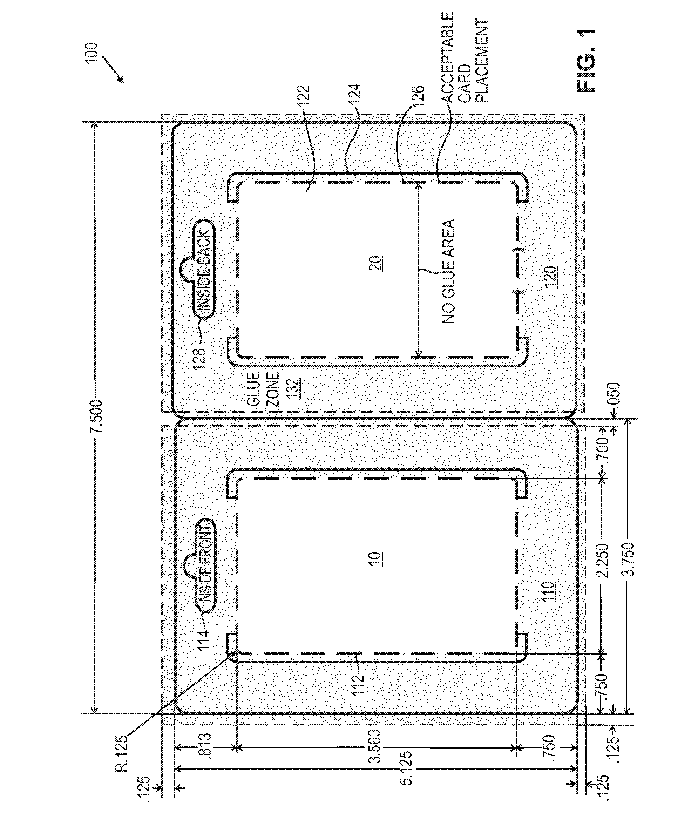
[0013]FIG. 1 shows a card carrier blank utilized to form a gift card carrier 100 in accordance with the present invention. More specifically, FIG. 1 shows a bi-panel arrangement in which a first panel 110 and a second panel 120 are folded about a centerline 130 and glued shut to form a gift card carrier as described in further detail below. Illustrative dimensions are included in FIG. 1 for the gift card carrier 100 for use with a gift card which is the size of a standard credit card. A presently preferred material for carrier 100 is 8 point or 12 point white paper having a nominal thickness of 0.0008″ or 0.012″, respectively. It will be recognized that other dimensions may be suitably employed for cards having other dimensions and that materials other than paper may be suitably employed.

[0014]First panel 110 has a rectangular area 112 where a terms and condition pamphlet or other product literature insert 10 may be suitably attached with fugitive glue, for example, which allows the...

second embodiment

[0019]Aspects of a card carrier in accordance with the present invention are illustrated in FIG. 4. In FIG. 4, a top fold tablet card carrier 400 is illustrated. Similar to the embodiment of FIG. 1, a first panel 410 includes a first area 412 reserved for a gift card. No card is shown in FIG. 4. First panel 410 also includes a first larger hangtag cutout 414. Additionally, the first panel 410 includes a cutout 450 which can be seen through red glassine sheet 460 which covers it.

[0020]Second panel 420 has a first area 422 reserved for attaching a terms and conditions pamphlet or other product literature insert. No product literature is shown in FIG. 4. A second area 424 defines a glue region. Second panel 420 also includes a second smaller hangtag cutout 428.

[0021]In this second embodiment, glue is applied around the edges of second panel 420 in either of the two ways described above in connection with FIG. 1. The red glassine sheet 460 is attached over cutout 450 then a gift card is...

third embodiment

[0022]FIG. 5 shows a card carrier 500 in accordance with the present invention. In FIG. 5, a first panel 510 of 12 point white paper and a separate second panel 520 of 12 point white paper are shown. For standard credit card sized gift cards, the dimensions of these two panels will preferably be the same as those shown for panels 110 and 120 in FIG. 1, respectively. Panel 510 has a first smaller hangtag cutout 514. Panel 520 has a second larger hangtag cutout 528. As addressed above, it will be recognized that other thicknesses of paper may be employed in place of 12 point white paper and so long as the overall bottom thickness of will be readable with a standard magstripe reader with an approximately 30 mil reader head spacing.

[0023]First panel 510 has a rectangular area 512 where a terms and conditions pamphlet or other product literature insert 10 may be suitably attached with fugitive glue, for example, which allows the booklet to be readily removed by a customer that purchases ...


PUM

PropertyMeasurementUnit
thicknessaaaaaaaaaa
areaaaaaaaaaaa
optical propertiesaaaaaaaaaa

Abstract

Techniques for providing cost effective and tamper evident prepaid card packaging are described. By forming a cutout in a panel of the prepaid card packaging, covering the cutout with a material such as red glassine, and aligning an activation bar code or other indicia on the card with the cutout when mounting the card within the packaging, the security of the activation indicia can be better maintained. After purchase, the bar code can be scanned through the red glassine but prior to purchase, the red glassine prevents photocopying.

Description

FIELD OF INVENTION[0001]The present invention relates generally to improvements in prepaid card packaging and activation, and more particularly to advantageous aspects of packaging of prepaid cards in a tamper evident manner to reduce fraud.BACKGROUND OF THE INVENTION[0002]As prepaid cards have become more and more prevalent, techniques for cost effectively packaging such cards in a tamper evident manner are highly desirable. While a wide variety of previous approaches have been tried, many such approaches have failed to provide the right balance of features. For example, a highly secure package may be too hard to open by a legitimate customer after purchase, too expensive or both. A very cost effective package may be too susceptible to fraud.[0003]Additionally, according to one aspect of many prepaid card systems, a bar code is scanned utilizing a bar code scanner at the time of sale of the card as part of the activation process for the card. Where the bar code is externally on the...

Claims


Application Information

Patent Timeline
Patent Type & Authority Applications(United States)
IPC IPC(8): B65D85/00B31B1/25B23P11/00B32B38/10B32B38/00B31B50/25
CPCB42D15/045B65D75/20B65D2203/06B65D2203/10Y10T156/1051Y10S283/904Y10T156/1062Y10T29/49826Y10S206/807Y10T83/0341
Inventor ABELL, DAVID GARLAND
Owner IDEMIA AMERICA CORP
Why Eureka
Try Eureka