Bit holders

Inactive Publication Date: 2010-09-09
WESTPORT MEDICAL
View PDF63 Cites 232 Cited by
  • Summary
  • Abstract
  • Description
  • Claims
  • Application Information

AI Technical Summary

Problems solved by technology

Some bit holders may require manipulation by the user to secure and / or unsecure the desired bit to the bit holder.

Method used


Image

  • Bit holders
  • Bit holders
  • Bit holders

Examples


Embodiment Construction

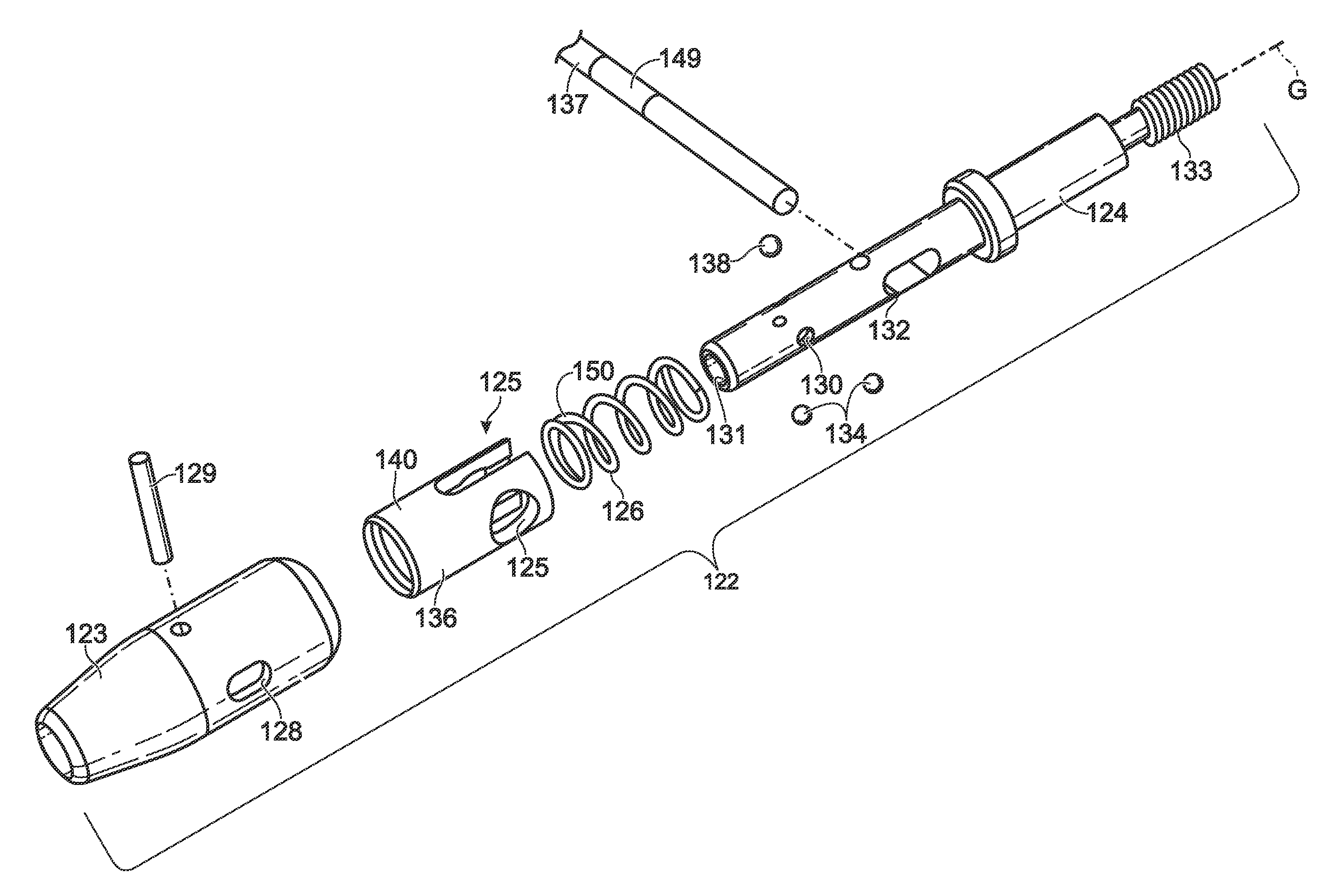
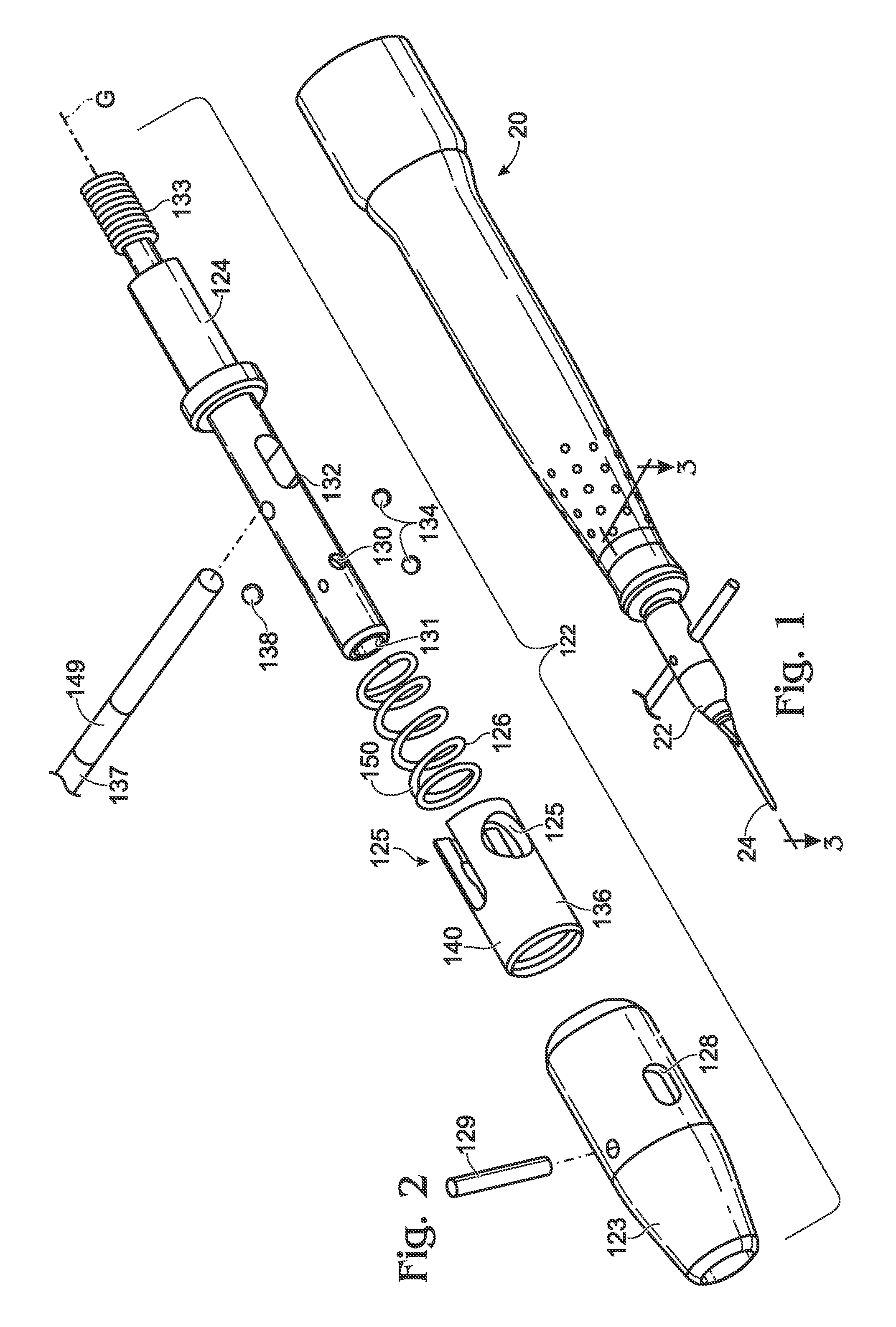
[0013]FIG. 1 depicts a powered surgical instrument 20 having a bit holder 22 that removably secures a bit 24. The powered surgical instrument may have any suitable structure and / or may have any suitable function(s). For example, powered surgical instrument 20 may include at least some of the components described in U.S. Patent Application Publication No. 2006 / 0014119. The complete disclosure of that publication is herein incorporated by reference for all purposes. Although powered surgical instrument 20 is shown to include bit holder 22, any suitable powered and / or manual instrument may include the bit holder.

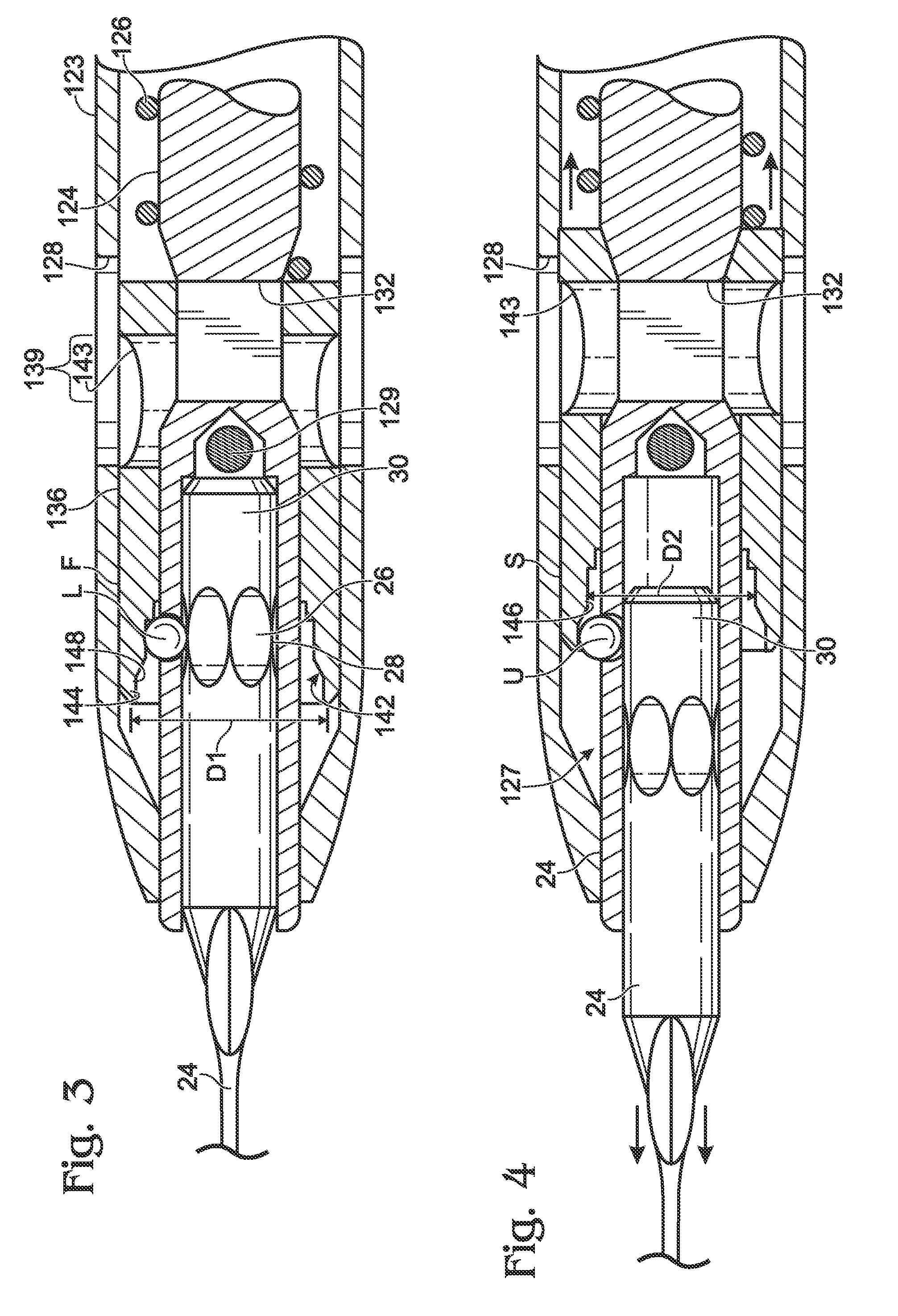
[0014]Bit 24 may include one or more first locking elements 26 (as shown in FIG. 3), which may include, any suitable structure configured to interact with one or more locking mechanisms of the bit holder. For example, first locking elements 26 may include one or more indentations, depressions, or grooves 28. Grooves 28 may include any suitable shape(s). For example, the grooves...


PUM


Abstract

A holder for a bit is disclosed. The bit may include a first locking element. The holder may include a housing; a base assembly including a first hole; a second locking element partially disposed within the first hole and configured to move between a locking position in which the second locking element engages the first locking element to prevent removal of the bit, and an unlocking position in which the second locking element is spaced from the first locking element allowing the bit to be removed; and a follower assembly contained within the housing and configured to move relative to the housing and base assembly between a first position in which the follower assembly supports the second locking element in the locking position, and a second position in which the follower assembly allows the second locking element to move from the locking position to the unlocking position.

Description

CROSS-REFERENCE TO RELATED APPLICATIONS [0001]This application claims priority under 35 U.S.C. §119(e) to U.S. Provisional Patent Application Ser. No. 61 / 209,137 entitled “Bit Holders,” filed Mar. 3, 2009. The complete disclosure of the above application is herein incorporated by reference for all purposes.BACKGROUND OF THE DISCLOSURE [0002]Various powered and / or manual instruments may use one or more removable tool bits, which may have different shapes and / or designs to accomplish different tasks. The instruments typically will include a bit holder to removably hold and / or secure one or more of the bits. Some bit holders may require manipulation by the user to secure and / or unsecure the desired bit to the bit holder. For example, a conventional three-jaw chuck requires the user to loosen the jaws to insert or remove the bit and to tighten the jaws to secure the bit. Other bit holders may automatically secure and / or lock the bit when the user inserts the bit into the bit holder. Alt...

Claims


Application Information

Patent Timeline
Patent Type & Authority Applications(United States)
IPC IPC(8): B23B31/171B23B31/22
CPCA61B17/162A61B2017/00473A61C1/142B23B31/1071B23B2260/078B25B23/0035Y10T279/17521Y10T279/3481Y10T279/32Y10T279/17752Y10T279/17145Y10T279/17196Y10T279/17461Y10S279/905
Inventor PORTER, DOUGLAS ROYBRAUNBERGER, JASON DEAN
Owner WESTPORT MEDICAL
Why Eureka
Try Eureka