
Foam Filler For Placement Between Automobile Seats

a filler device and filler technology, which is applied in the field of automobile seat filler, can solve the problems of difficult to remove refuse, prevent the seat from moving forward or backward, and lodged coins, papers, pens,

Inactive Publication Date: 2010-09-16
MANLEY JACK M
View PDF18 Cites 19 Cited by
  • Summary
  • Abstract
  • Description
  • Claims
  • Application Information

AI Technical Summary

Benefits of technology

[0006]The disclosure is directed to a filler device for placement between a seat and console. The device comprises a one-piece body. The body has an elongate blade with an upper portion of substantially uniform width throughout its length, and a wedge-shaped lower portion. The body is adapted for insertion in a crevice between an automobile seat cushion and an automobile con

Problems solved by technology

Coins, papers, pens, and debris are often lodged or lost in a crevice between an automobile seat, such as a driver seat, and a storage console in an automobile.
Since the crevice is narrow and cannot be reached by adult-sized hands, it is difficult for the refuse to be removed.
As items continue to fall into the crevice the refuse accumulates on the floor of the automobile and can possibly become lodged in seat tracks disposed under the seats, preventing the seat from moving forward or backward.
Spilled beverages, food particles, and anything perishable can be particularly problematic because these substances may scatter or dissolve upon impacting the vehicle carpet and may cause the passenger compartment to smell.
However, because it is generally not possible to see down into the crevice, people injure their hands on the sharp metal or plastic edges of vehicle seat parts or seat tracks during this process.
Personal jewelry such as rings, watches, bracelets and other items also frequently catch on seat and seat track components thereby trapping the hands of the cleaner.
In addition to the problems associated with cleaning the crevice, many people also create a safety hazard by trying to retrieve dropped items such as cell phones, pens, eyewear, etc. from between seats and consoles while driving.

Method used


Image

  • Foam Filler For Placement Between Automobile Seats
  • Foam Filler For Placement Between Automobile Seats
  • Foam Filler For Placement Between Automobile Seats

Examples


Embodiment Construction

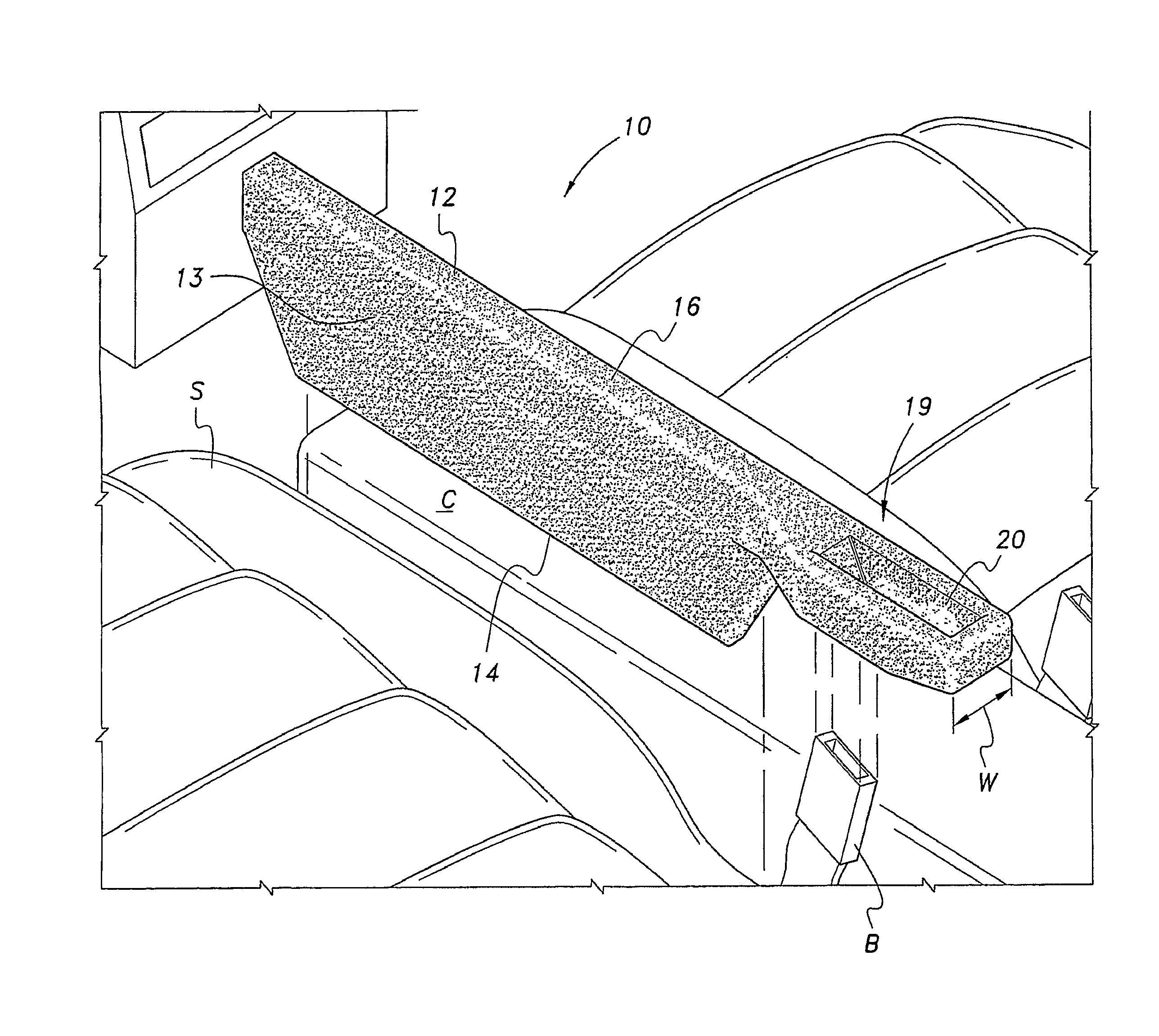
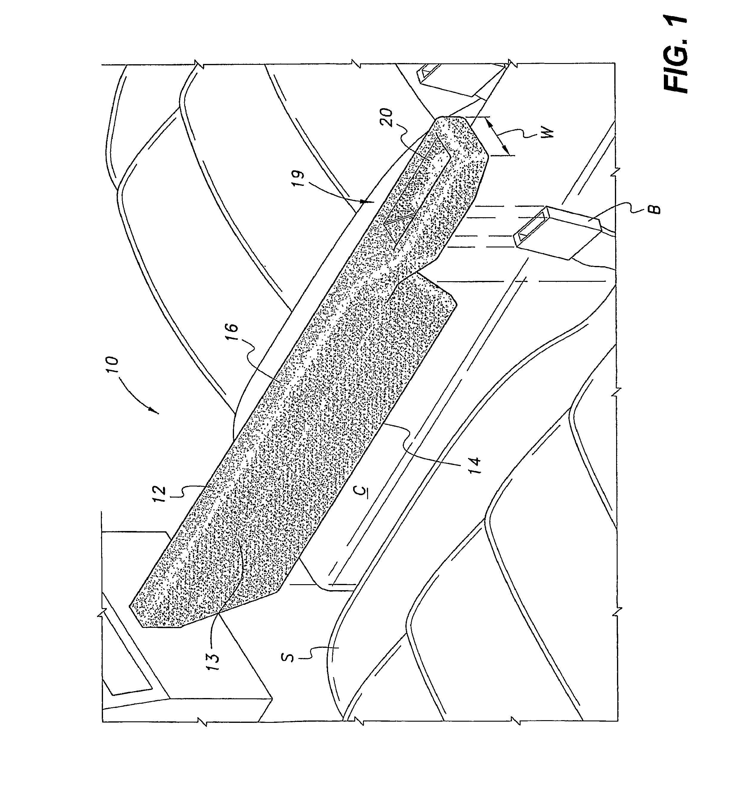
[0014]As generally shown in FIG. 1, the filler 10 comprises an elongate blade 16 and a seat belt boss 19 that extends from the blade 16. In the preferred embodiment, the boss 19 extends longitudinally in the same plane as the blade 16. The blade 16 has an upper portion 12 of substantially uniform width throughout its length, and a wedge-shaped lower portion 13 that tapers down to a thin bottom edge 14 so that the device 10 is adapted for insertion between the automobile seat cushion S and the console C. The seat belt boss 19 has a greater width than the blade upper portion 12 and defines an opening 20 through which a seat belt buckle receiver B may be inserted to retain the filler 10 wedged in place. The seat belt boss 19 is preferably positioned adjacent the area in which seat belt receptacle B emanates.

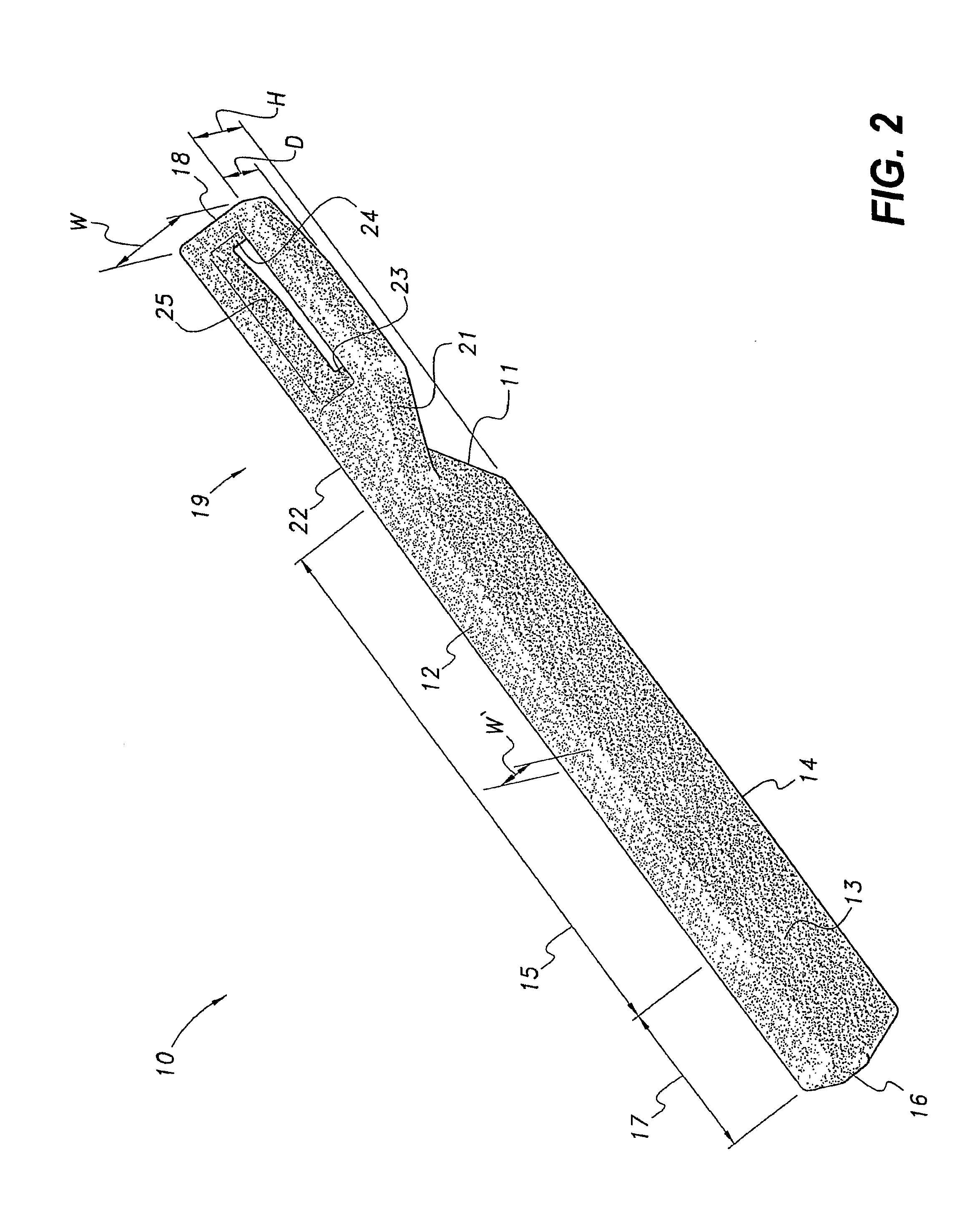
[0015]As best shown in FIG. 2, the filler blade upper portion 12 extends longitudinally to form a front section 17, and a rear section 15. In a preferred embodiment, a longitudinal ...


PUM


Abstract

The filler device for placement between seats / consoles is a one-piece, rugged polymer body (10) having an elongate blade and a seat belt boss extending either rearward or laterally from the blade. The blade has an upper portion (12) of substantially uniform width throughout its length, and a wedge-shaped lower portion (13) adapted for insertion between the automobile seat cushion and a console (C). The seat belt boss has a greater width than the blade and defines an opening (20) through which the buckle receiver (B) of a seat belt may be inserted to retain the filler wedged in place. In alternative embodiments, the filler (10) may have a cell phone holder or a cup holder extending laterally from the front end of the blade.

Description

TECHNICAL FIELD[0001]The present invention relates to motor vehicle accessories, and more particularly to a filler device for placement between the seat and console of an automobile.BACKGROUND ART[0002]Coins, papers, pens, and debris are often lodged or lost in a crevice between an automobile seat, such as a driver seat, and a storage console in an automobile. Since the crevice is narrow and cannot be reached by adult-sized hands, it is difficult for the refuse to be removed. As items continue to fall into the crevice the refuse accumulates on the floor of the automobile and can possibly become lodged in seat tracks disposed under the seats, preventing the seat from moving forward or backward. Spilled beverages, food particles, and anything perishable can be particularly problematic because these substances may scatter or dissolve upon impacting the vehicle carpet and may cause the passenger compartment to smell.[0003]The present invention is also designed to prevent injury to autom...

Claims


Application Information

Patent Timeline
IPC IPC(8): B60N2/44B60N2/90
CPCB60N2/6009B60N3/103B60N2/7005
Inventor MANLEY, JACK M.
Owner MANLEY JACK M
Learn More