Tape Printing Apparatus and Tape Cassette

a printing apparatus and tape cassette technology, applied in the field of tape printing apparatus, can solve the problems of inability to print across the entire length of the label in a single pass, trailers are usually not desirable, and blank regions are noticeabl

Inactive Publication Date: 2010-09-16
DYMO (BVBA)
View PDF10 Cites 77 Cited by
  • Summary
  • Abstract
  • Description
  • Claims
  • Application Information

AI Technical Summary

Benefits of technology

[0014]According to a third aspect of the present invention there is provided a tape printer comprising a cassette receiving portion for receiving a cassette containing image receiving tape, a print head for printing an image on a tape, a first support...

Problems solved by technology

However, printing across the entire length of the label in a single pass is not currently possible due to the location of the cutter in relation to the location of the print head. FIG. 1 (a) shows the relative positions of the print head (60), the platen (80), the cutter (20) and the image receiving tape (44) in a tape printing apparatus during printing. FIG. 1 (b) shows the position of the tape (40) at various stages of printing.
However a blank leader and trailer are usually not desirable, especially when labels are printed with a background therefore making the blank regions noticeable.
The inclusion of rollers increases the size of the printer and the complexity of the driving mechanism.
Using rollers upstream of the print head to feed the tape between the print head and the platen c...

Method used


Image

  • Tape Printing Apparatus and Tape Cassette
  • Tape Printing Apparatus and Tape Cassette
  • Tape Printing Apparatus and Tape Cassette

Examples


Embodiment Construction

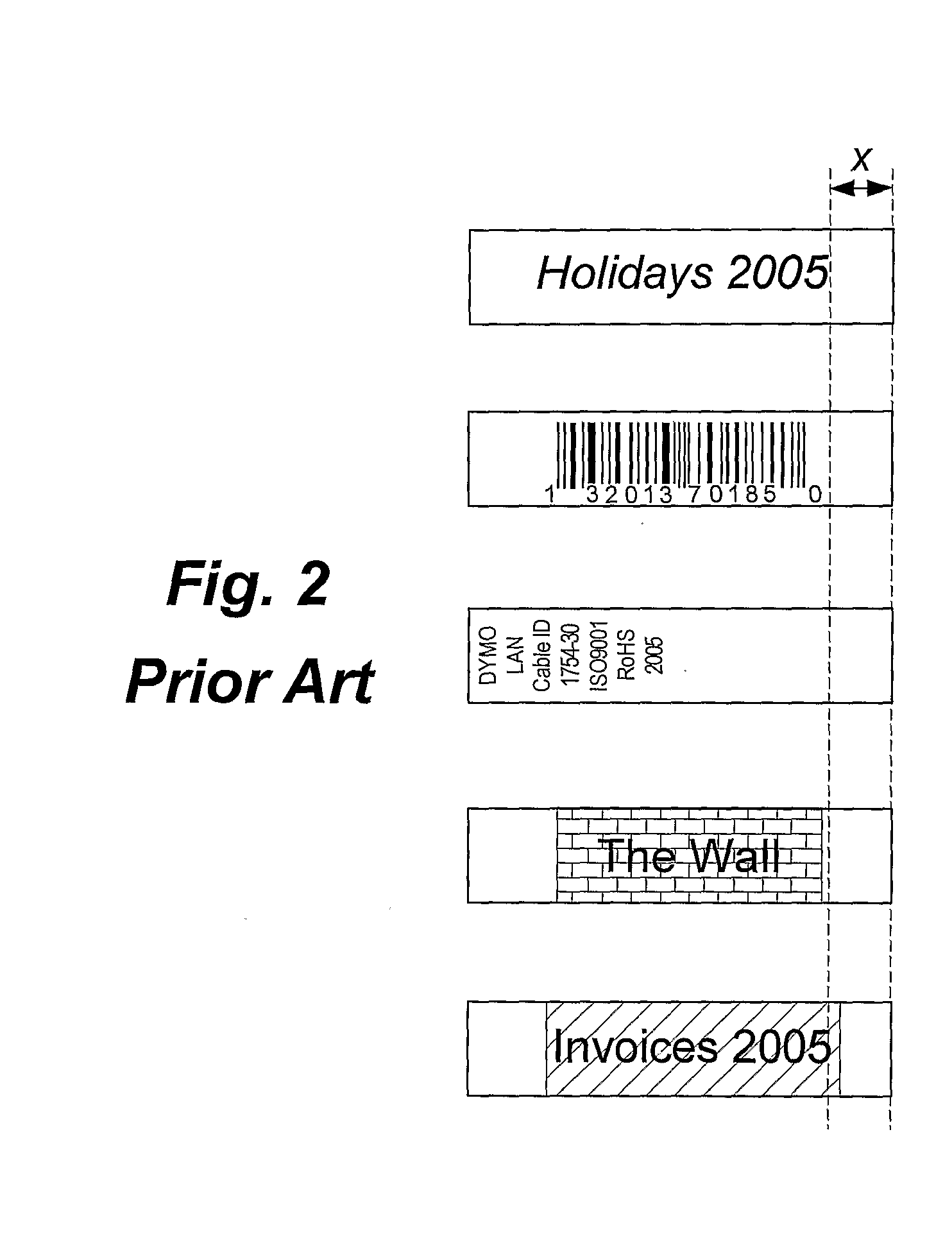
[0031]FIGS. 1 and 2 indicate prior art and have already been discussed in the preamble of this specification.

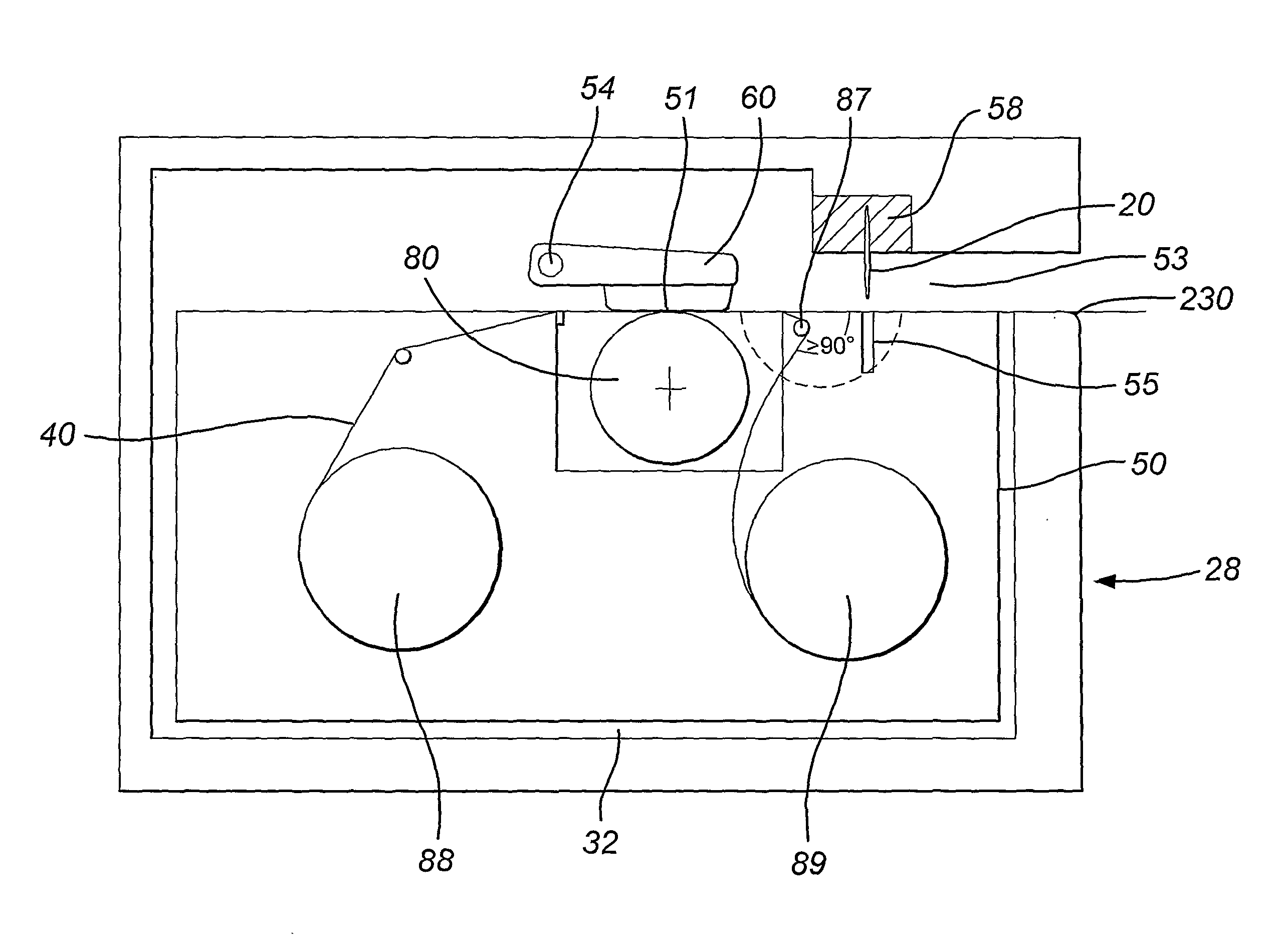
[0032]FIG. 3 shows a schematic diagram of a tape printing apparatus 28 according to an embodiment of the present invention. The tape printing apparatus comprises a keyboard 30 and a cassette receiving bay 32. The keyboard has a plurality of data entry keys 34 such as numbered, lettered and punctuation keys for inputting data to be printed as a label and function keys for editing the input data. The keyboard may also have a print key 36 which is operated when it is desired that a label be printed. Additionally an on / off key 38 is also provided for switching the tape printing apparatus on and off.

[0033]The tape printing apparatus has a liquid crystal display (LCD) 10 which displays the data as it is entered. The display allows the user to view all or part of the label to be printed which facilitates the editing of the label prior to its printing. Additionally, the display is ...


PUM

PropertyMeasurementUnit
Lengthaaaaaaaaaa
Lengthaaaaaaaaaa
Angleaaaaaaaaaa

Abstract

A composite tape supply for use in a tape printer comprising an image receiving layer; a backing layer; and a liner layer.

Description

FIELD OF THE INVENTION[0001]The present invention relates to a tape printing apparatus, a composite tape supply and to a method of printing on a composite tape to form a label. In particular, the present invention relates to a tape printing apparatus for printing an image, such as a background image, so that the image is printed across the length of the entire label.BACKGROUND OF THE INVENTION[0002]Printers capable of printing background images include direct thermal printers.[0003]For example, EP 1638780 describes a method of printing a label in which a multicoloured image is produced on the tape by direct thermal transfer in a single pass of the tape past the print head, resulting in a high quality colour image.[0004]When printing a colour background such as a single block colour, it is possible to print a background which covers the entire width of the label since the width of the print head exceeds the width of the tape. However, printing across the entire length of the label in...

Claims


Application Information

Patent Timeline
IPC IPC(8): B41J11/42B41J15/04
CPCB41J3/4075B41J15/044B41J11/42B32B3/16B32B2519/00B32B2367/00B32B43/006B32B43/003B32B2323/04B32B2317/12B32B27/10B32B38/145B32B27/32B32B7/12
Inventor VANDERMEULEN, KRIS
Owner DYMO (BVBA)
Why Eureka
Try Eureka