Drive force adjustment apparatus

Active Publication Date: 2010-09-16
MITSUBISHI MOTORS CORP
View PDF3 Cites 15 Cited by
  • Summary
  • Abstract
  • Description
  • Claims
  • Application Information

AI Technical Summary

Benefits of technology

[0005]It is therefore an object of the invention to provide a drive force adjustment apparatus capable of preventing the

Problems solved by technology

However, in the drive force adjustment apparatus according to the related art disclosed in JP-A-2006-112474, there is a problem that since the number of revolutions of a second sun gear, which is disclosed in JP-A-2006-112474, changes due to the turning direction of a vehicle and a difference in the number of revolutions between the left wheel and the right wheel, the traveling load changes and the turning

Method used


Image

  • Drive force adjustment apparatus
  • Drive force adjustment apparatus
  • Drive force adjustment apparatus

Examples


Example

Embodiment 1

[0186]Hereinafter, a description is given of Embodiment 1 of the drive force adjustment apparatus according to the present invention.

[0187]Based on the result of the above-described examination, the drive force adjustment apparatus according to the present embodiment has been configured so as to achieve the A / SC type that is capable of taking a greater value than 1 for the system gain G and in which the number NC of revolutions is fixed and always takes a positive value.

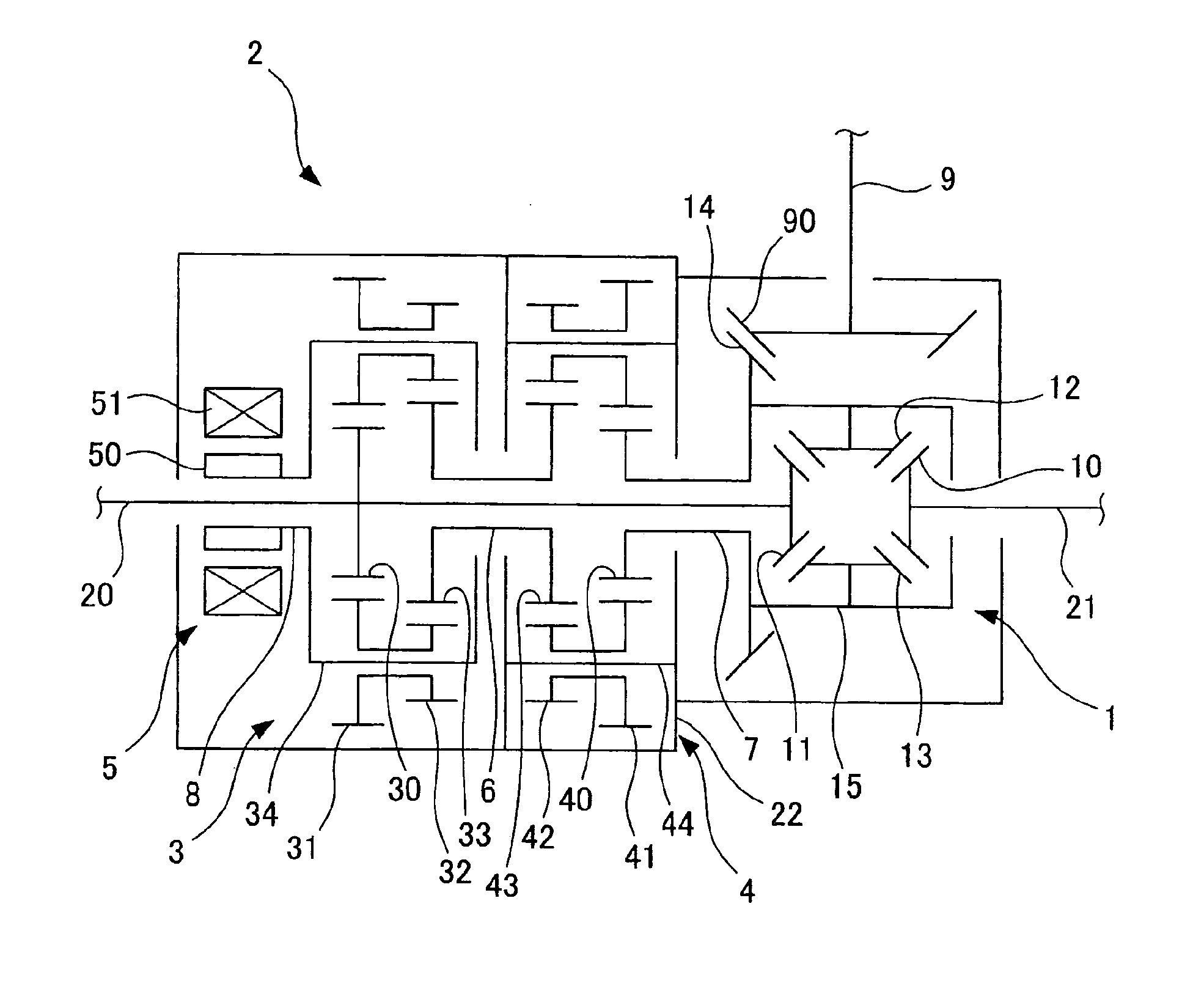
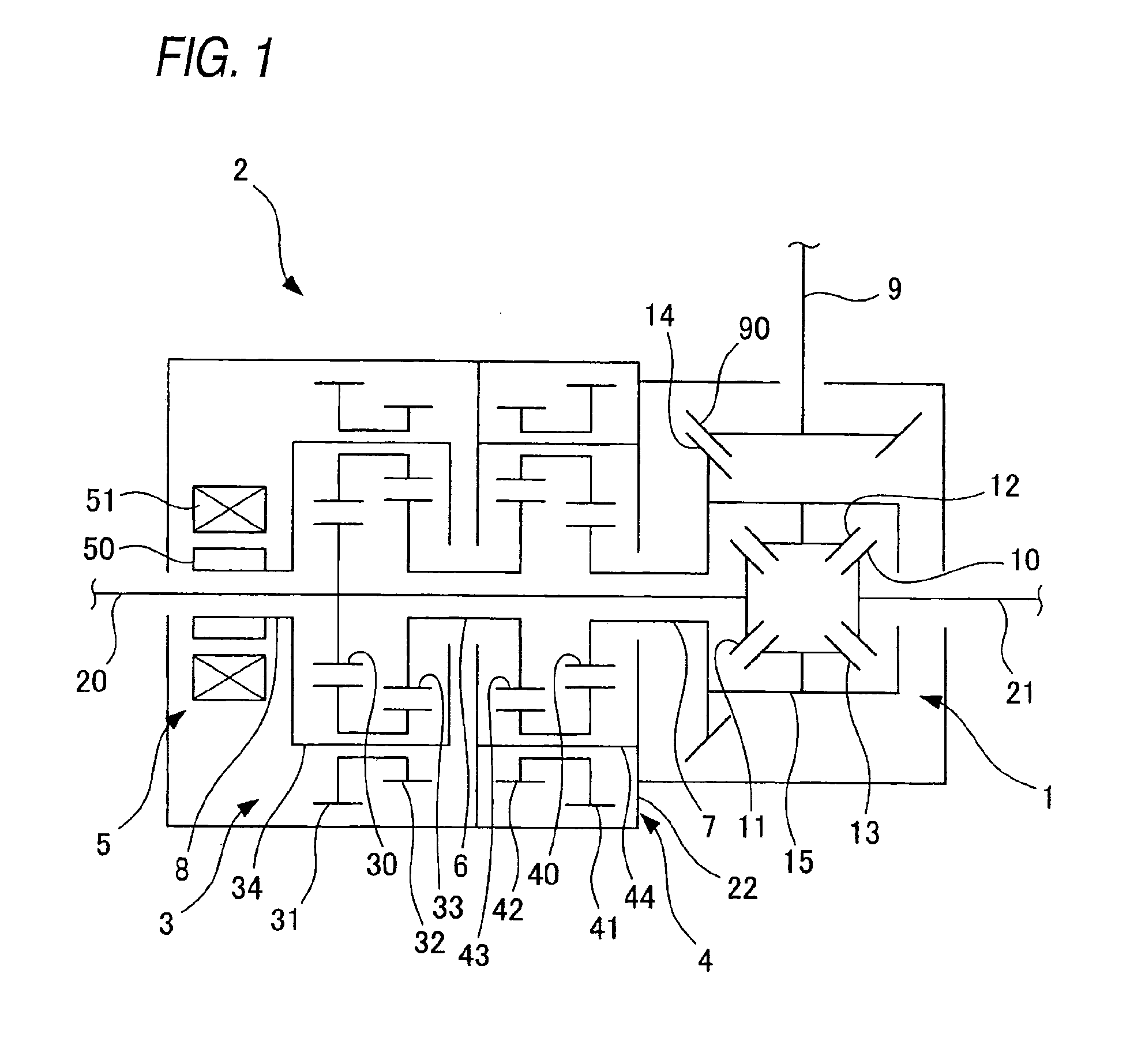
[0188]FIG. 1 is a skeleton diagram of a drive force adjustment apparatus according to Embodiment 1.

[0189]As shown in FIG. 1, a differential gear 1 is provided with a left and right wheel drive force adjustment mechanism 2 capable of adjusting a drive force distribution transmitted to the left wheel and the right wheel. In the present embodiment, the differential gear 1 uses a bevel gear type differential apparatus according to the related arts.

[0190]The differential gear 1 is provided with left and right ...

Example

Embodiment 2

[0211]Hereinafter, a description is given of Embodiment 2 of the drive force adjustment apparatus according to the present invention.

[0212]The drive force adjustment apparatus according to the present embodiment differs from the drive force adjustment apparatus according to Embodiment 1 in that a motor 5 is installed sideways of the left and right wheel drive force adjustment mechanism 2 in the front and rear direction of a vehicle.

[0213]FIG. 3 is a skeleton diagram of the drive force adjustment apparatus according to Embodiment 2.

[0214]As shown in FIG. 3, in the drive force adjustment apparatus according to the present embodiment, the motor 5 is installed sideways of the left and right wheel drive force adjustment mechanism 2 in the front and rear direction of a vehicle, a gear 52 is installed at the rotor 50, and a gear 53 meshed with the gear 52 is installed on the outer circumferential side of the hollow shaft 8, wherein the motor 5 and the left and right wheel drive...

Example

Embodiment 3

[0216]Hereinafter, a description is given of Embodiment 3 of the drive force adjustment apparatus according to the present invention.

[0217]Based on the result of the above-described examination, the drive force adjustment apparatus according to the present embodiment has been configured so as to achieve the X / SC type in which the number NC of revolutions is fixed and the number NC of revolutions is always smaller than the number of revolutions of the case of the differential gear. Also, the configuration of the drive force adjustment apparatus according to the present embodiment is the same as that of the drive force adjustment apparatus according to Embodiment 1 except for the configuration of the left and right wheel drive force adjustment mechanism.

[0218]FIG. 4 is a skeleton diagram of the drive force adjustment apparatus according to Embodiment 3.

[0219]As shown in FIG. 4, the left and right wheel drive force adjustment mechanism 2 in the drive force adjustment appara...


PUM


Abstract

A drive force adjustment apparatus includes a differential gear, a motor, a first gear mechanism and a second gear mechanism. The input element, the first output element, the second output element, the motor input element, the fixed element, and the connecting element are expressed as points I, R, L, M, F and C on a graph, a ordinate of which shows the number of revolutions and a abscissa of which shows relative ratios of the number of revolutions of the elements. Length of L-I is equal to length of R-I, I is located between L and R on a straight line L-R, C is located between L and M on a straight line L-M, and C is located between F and I on a straight line F-I. Or, length of L-I is equal to length of R-I, I is located between L and R on a straight line L-R, C is located between R and M on a straight line R-M, and C is located between F and I on a straight line F-I.

Description

BACKGROUND OF THE INVENTION[0001]The present invention relates to a drive force adjustment apparatus.[0002]A drive force adjustment apparatus of a related art, which adjusts distribution of drive force to the left and right wheels of a vehicle, has been known. In the drive force adjustment apparatus, a drive force adjustment mechanism is provided along with a differential gear between the left and right drive wheels, and a drive force distribution state is controlled by controlling actuation of the drive force adjustment mechanism. Such a configuration has been known as the drive force adjustment mechanism, which is provided with two gear mechanisms for further increasing or further decreasing the velocity of one wheel of the left and right wheels than that of the other wheel and a motor for generating a difference in torque between the left wheel and the right wheel by distributing torque to the left and right wheels. One example of such a related art is disclosed in JP-A-2006-1124...

Claims


Application Information

Patent Timeline
IPC IPC(8): F16H37/08B60K23/04F16H48/30F16H48/38
CPCB60K17/165F16H48/08F16H2048/364F16H48/36F16H48/30
Inventor KATO, TOMOSAWASE, KAORUUSHIRODA, YUICHI
Owner MITSUBISHI MOTORS CORP
Why Eureka
Try Eureka