Toilet stool for odor removal which applies the reserving energy as power source

a technology of power source and toilet stool, applied in the field of toilet stool for odor removal, can solve the problems of making the surrounding persons unpleasant, sound stimulating the user's nerves, and trouble, and achieve the effects of reducing mechanical driving sound, reducing manufacturing cost, and improving product duration

a technology of power source and toilet stool, applied in the field of toilet stool for odor removal, can solve the problems of making the surrounding persons unpleasant, sound stimulating the user's nerves, and trouble, and achieve the effects of reducing mechanical driving sound, reducing manufacturing cost, and improving product duration

US20100242161A1Inactive Publication Date: 2010-09-30YOO KWANG TAE

Image

  • Toilet stool for odor removal which applies the reserving energy as power source
  • Toilet stool for odor removal which applies the reserving energy as power source
  • Toilet stool for odor removal which applies the reserving energy as power source

Examples


Embodiment Construction

[0029]Other objects and advantages of the present invention can be understood by the following description, and become apparent with reference to the embodiments of the present invention.

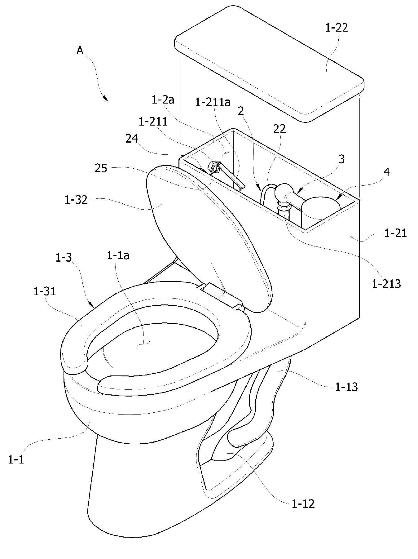
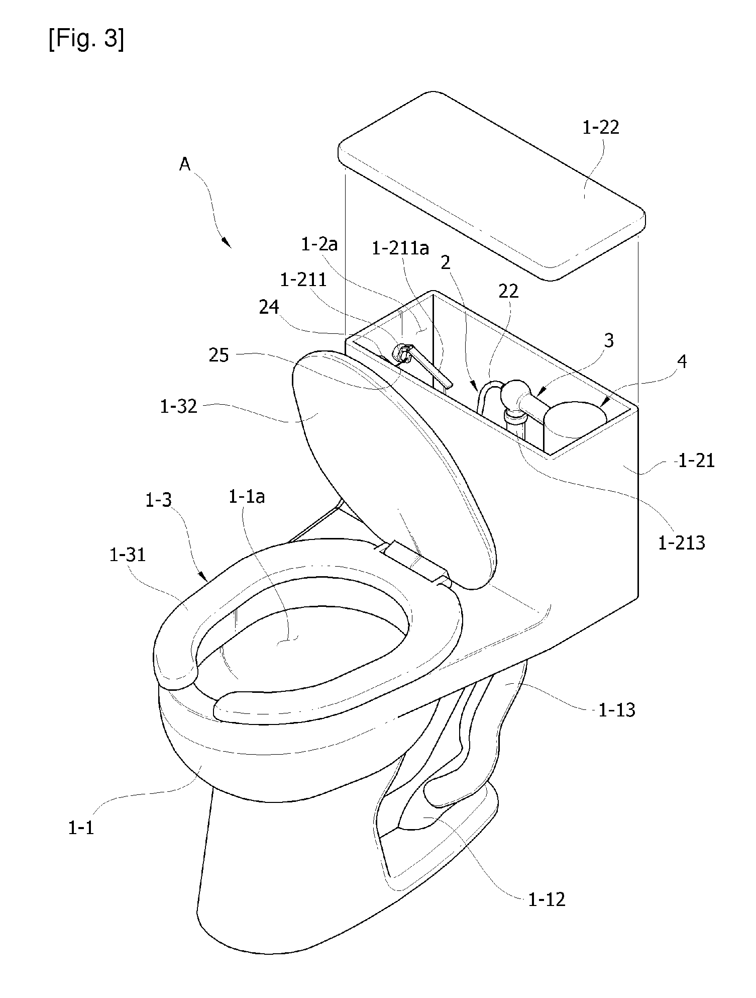
[0030]Here, among the accompanying drawings, FIGS. 3 and 4 are exploded perspective view and side-cross sectional view, respectively illustrating a constitutional relationship of the odor removal toilet stool using a preserving energy as a power source according to the present invention, FIGS. 5 and 6 are front-sectional view and top-sectional view, respectively illustrating a inner configuration of a water storage tank mounted to the odor removal toilet stool using a preserving energy as a power source according to the present invention, FIG. 7 is a perspective view illustrating an assembled state of a suction power means, a fluid operation tube, and a bad smell air discharge means in the odor removal toilet stool using a preserving energy as a power source according to the present invention, FIG. ...


PUM


Abstract

The present invention relates to a odor removal toilet stool, and more particularly, to a odor removal toilet stool using a preserving energy as a power source, capable of removing bad smell air and preventing its back flow in which the cleaning water (supplying water) stored in a water storage tank is supplied at two stages such as an initial standby water level and later full water level, wherein during supplying water to the full water level, air transference method using hydrodynamic operation occurred from a high speed injection with a injection nozzle is used without electric energy. According to the present invention, there is provided with an odor removal toilet stool using a preserving energy as a power source consisting of a stool body for containing feces and urine and discharging them to a water purifier tank, a water storage tank for storing a cleaning water used for discharging the excrement, which is provided on external part thereof with a water pouring button for draining the stored cleaning water, and a seat on which a user seats comfortably, comprises: a suction power means for supplying additionally the cleaning water into the water storage tank during a predetermined time period in order to absorb forcibly bad smell air within the stool body without a separate external power using a water saving effect based on different excreting time periods of each user and a standby pressure differences based on hydrodynamic operations; a fluid operation tube for allowing air movement such as an external discharging after absorbing forcibly the bad smell air in a state of instant vacuum caused from pressure difference of internal space which is occurred during supplementing the cleaning water through the suction power means; and a bad smell air discharging means wherein the fluid flowed-in through the fluid operation tube is separated naturally based on its specific gravity, and the bad smell air of fine particles rises as a rotation air current along the circular inner wall surface and then is discharged downward, and the fine water particles which is discharged together with the bad smell air forms a water film valve with water drops in order to prevent completely the finally discharged bad smell air from being back-flowed.

Description

TECHNICAL FIELD[0001]The present invention relates to a toilet stool for odor removal, and more particularly, to an improved odor removal toilet stool using a preserving energy as a power source, capable of removing bad smell air and preventing its back flow in which the cleaning water (supplying water) stored in a water storage tank is supplied at two stages such as an initial standby water level and later kill water level, wherein during supplying water to the kill water level, air transference method using hydrodynamic operation occurred from a high speed injection with a injection nozzle is used without electric energy.BACKGROUND ART[0002]Generally, a toilet stool refers to a western style flush toilet on which a person may astride and excrete wherein when excreting by using the toilet stool, the feces and urine excreted from the eliminatory organ inside body of a user make promptly bad smell air.[0003]In more detail, when a small amount of the excrement such as feces and urine ...

Claims


Application Information

Patent Timeline
30 Sep 2010
Publication
US20100242161A1
IPC
E03D1/00
CPC
E03D9/05; E03D9/04
Inventors
YOO, KWANG TAE