Image recording apparatus

Active Publication Date: 2010-09-30
BROTHER KOGYO KK
View PDF4 Cites 0 Cited by
  • Summary
  • Abstract
  • Description
  • Claims
  • Application Information

AI Technical Summary

Benefits of technology

[0007]This invention has been developed in view of the above-described situations, and it is an object of the present invention to provide an ima

Problems solved by technology

Thus, in the conventional technique, it is difficult to achieve both of the reduction of

Method used


Image

  • Image recording apparatus
  • Image recording apparatus
  • Image recording apparatus

Examples


Example

First Embodiment

Overall Construction of Printer

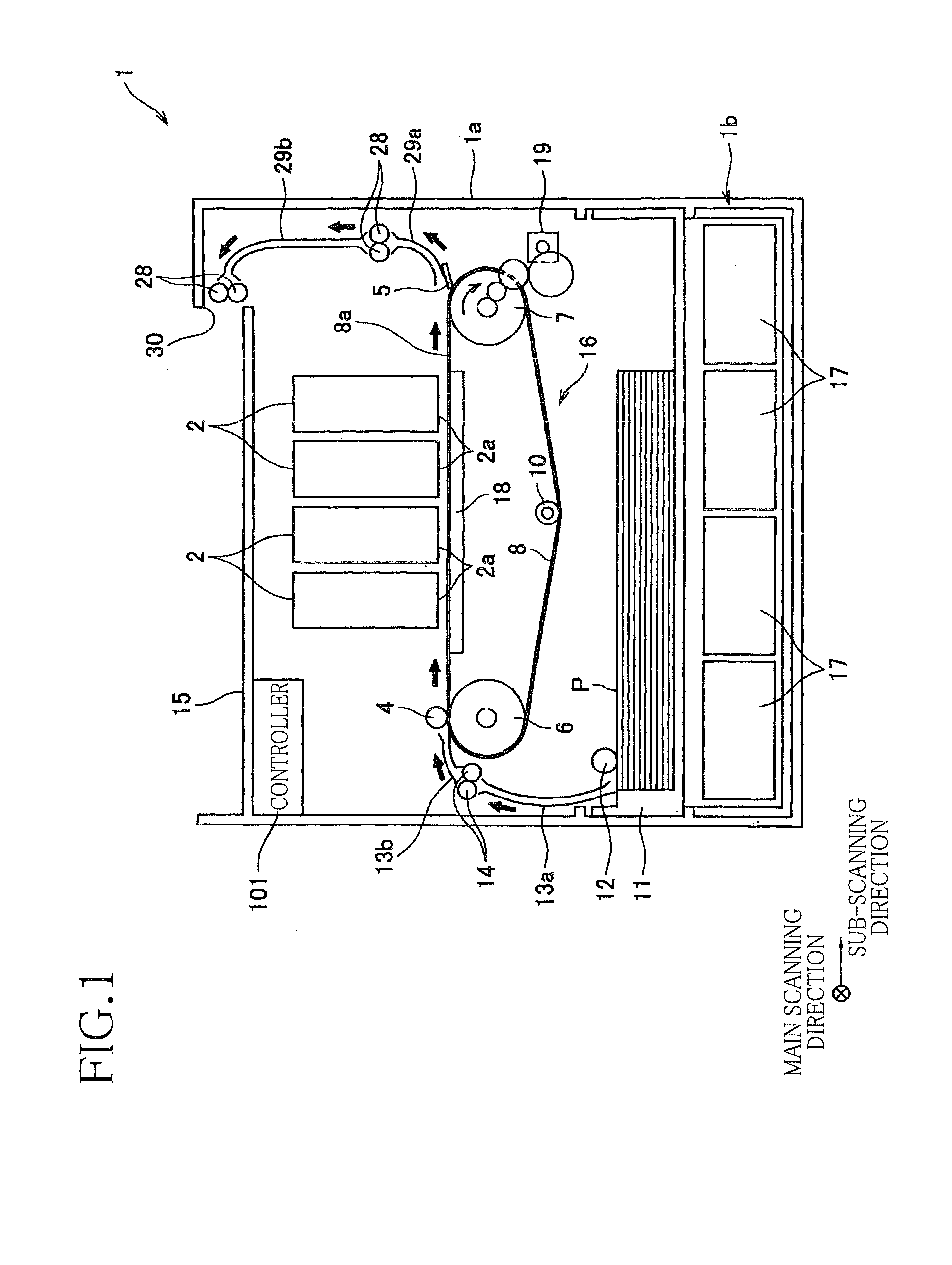
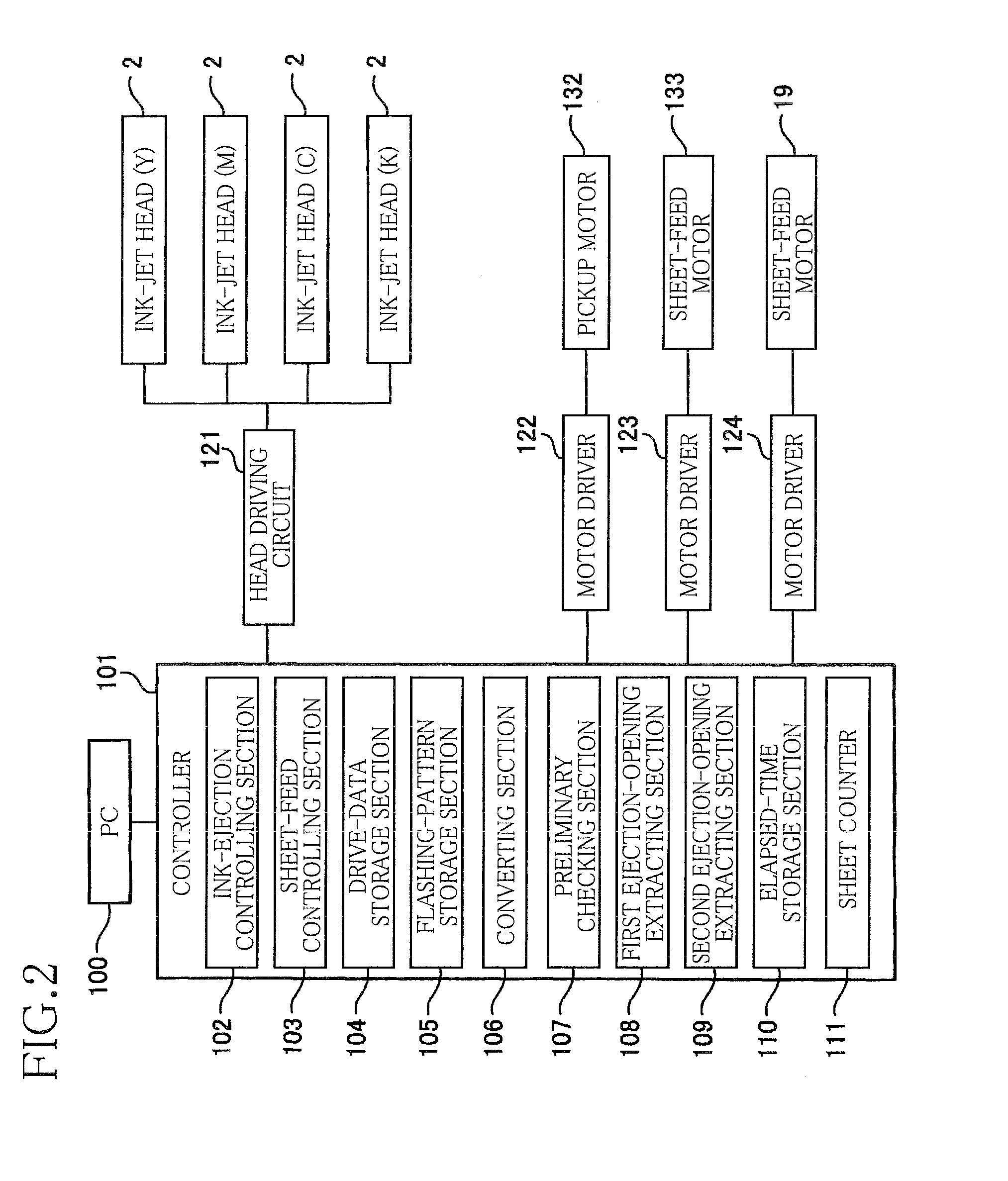
[0019]As shown in FIG. 1, an ink-jet printer 1 which is an image recording apparatus as a first embodiment of the present invention includes a casing 1a having a rectangular parallelepiped shape. In the casing 1a, there are disposed (a) four ink-jet heads 2 which respectively eject inks of four colors, namely, magenta, cyan, yellow, and black, and (b) a sheet-feed unit 16. A sheet-supply tray 11 attachable to and detachable from the casing 1a is disposed below the sheet-feed unit 16. An ink tank unit 1b attachable to and detachable from the casing 1a is disposed below the sheet-supply tray 11. A controller 101 which controls operations of the printer 1 is mounted on an inner surface of a top plate of the casing 1a. An upper surface of the top plate functions as a sheet-discharge portion 15 onto which a recorded sheet P which has already been recorded is discharged and placed. As shown in FIG. 2, the controller 101 is connected to a pers...

Example

Second Embodiment

[0073]There will be next explained a second embodiment of the present invention. In the present embodiment, the shift of the image in the main scanning direction in the first embodiment is replaced with 180-degree rotation. An overall construction of a printer in the present embodiment is the same as that in the above-described first embodiment. Thus, in the explanation of the present embodiment, the same reference numerals used in the first embodiment may be used for elements included in the printer in the present embodiment. Further, like in the first embodiment, the controller 101 functions as the ink-ejection controlling section 102, the sheet-feed controlling section 103, the drive-data storage portion 104, the flashing-pattern storage section 105, the converting section 106, the preliminary checking section 107, the first ejection-opening extracting section 108, the second ejection-opening extracting section 109, the elapsed-time storage section 110, the sheet...

Example

Third Embodiment

[0091]There will be next explained a third embodiment of the present invention. In the present embodiment, the shift of the image in the main scanning direction in the first embodiment is replaced with “the shift” and “the shift and the 180-degree rotation”. An overall construction of a printer in the present embodiment is the same as that in the above-described first embodiment. Thus, in the explanation of the present embodiment, the same reference numerals used in the first embodiment may be used for elements included in the printer in the present embodiment. Further, like in the first embodiment, the controller 101 functions as the ink-ejection controlling section 102, the sheet-feed controlling section 103, the drive-data storage portion 104, the flashing-pattern storage section 105, the converting section 106, the preliminary checking section 107, the first ejection-opening extracting section 108, the second ejection-opening extracting section 109, the elapsed-t...


PUM


Abstract

An image recording apparatus including: a head having openings; a sheet-moving mechanism; a drive-data storage portion storing drive data; a converting section which converts the drive data such that an image position adjustment is changed; a first extracting section which extracts at least one opening whose number of ejections during the recording on at least one sheet of a first number based on unconverted drive data is smaller than a second number; a second extracting section which extracts at least one opening whose number of ejections during the recording on at least one sheet of a third number based on converted drive data is smaller than a fourth number; and a controller which controls the ejection such that a preliminary ejection from at least one opening extracted by the first and second extracting sections is performed upon recordings based on the unconverted drive data and the converted drive data.

Description

CROSS REFERENCE TO RELATED APPLICATION[0001]The present application claims priority from Japanese Patent Application No. 2009-082586, which was filed on Mar. 30, 2009, the disclosure of which is herein incorporated by reference in its entirety.BACKGROUND OF THE INVENTION[0002]1. Field of the Invention[0003]The present invention relates to an image recording apparatus such as an ink jet printer.[0004]2. Description of the Related Art[0005]In an image recording apparatus including a liquid ejection head configured to eject liquid droplets onto a recording medium, there is a problem such as ink-ejection failure including lowering of an ejection speed, non-ejection, and unevenness of an ejection direction of the liquid droplets from ejection openings from which the liquid has not been ejected for a long time. In order to restrain the ink-ejection failure, in a conventional technique, a dummy jet (i.e., a preliminary ejection) is performed on a sheet from nozzles in which the ejection ha...

Claims


Application Information

Patent Timeline
IPC IPC(8): B41J29/38
CPCB41J29/38B41J2/1652
Inventor MURASHIMA, HIROSHI
Owner BROTHER KOGYO KK
Why Eureka
Try Eureka