Liquid ejection method and liquid ejecting apparatus

Active Publication Date: 2006-08-22
SEIKO EPSON CORP
View PDF2 Cites 2 Cited by
  • Summary
  • Abstract
  • Description
  • Claims
  • Application Information

AI Technical Summary

Benefits of technology

[0012]The present invention has been made in view of the circumstances mentioned above, and an object thereof is to

Problems solved by technology

However, in adopting the above-mentioned measure, ink will be wasted if the starting position and/or the terminating position for ejecting ink from the print head is determined without giving any consideration to the feed amount by which the print paper is fed using a paper feed motor after the position of the end of the print paper has been detected.
Despite such a fact, if the starting position or the terminating position for ejecting

Method used


Image

  • Liquid ejection method and liquid ejecting apparatus
  • Liquid ejection method and liquid ejecting apparatus
  • Liquid ejection method and liquid ejecting apparatus

Examples


first embodiment

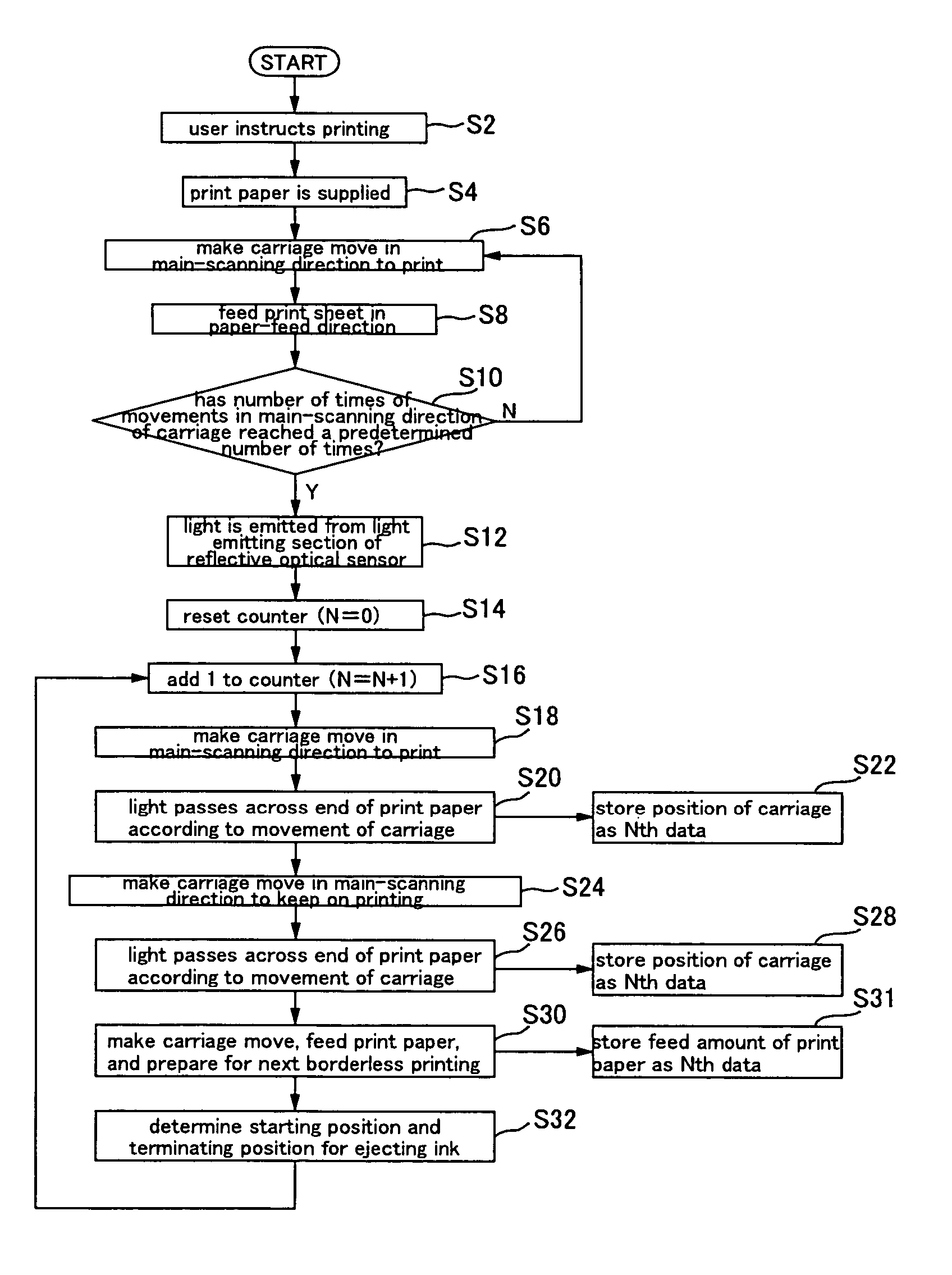
[0084]Next, a first embodiment of the present invention is described using FIG. 9A through FIG. 9F and FIG. 10. FIG. 9A through FIG. 9F are diagrams schematically showing positional relationships between the print head 36, the reflective optical sensor 29, and the print paper P. FIG. 10 is a flowchart for describing the first embodiment.

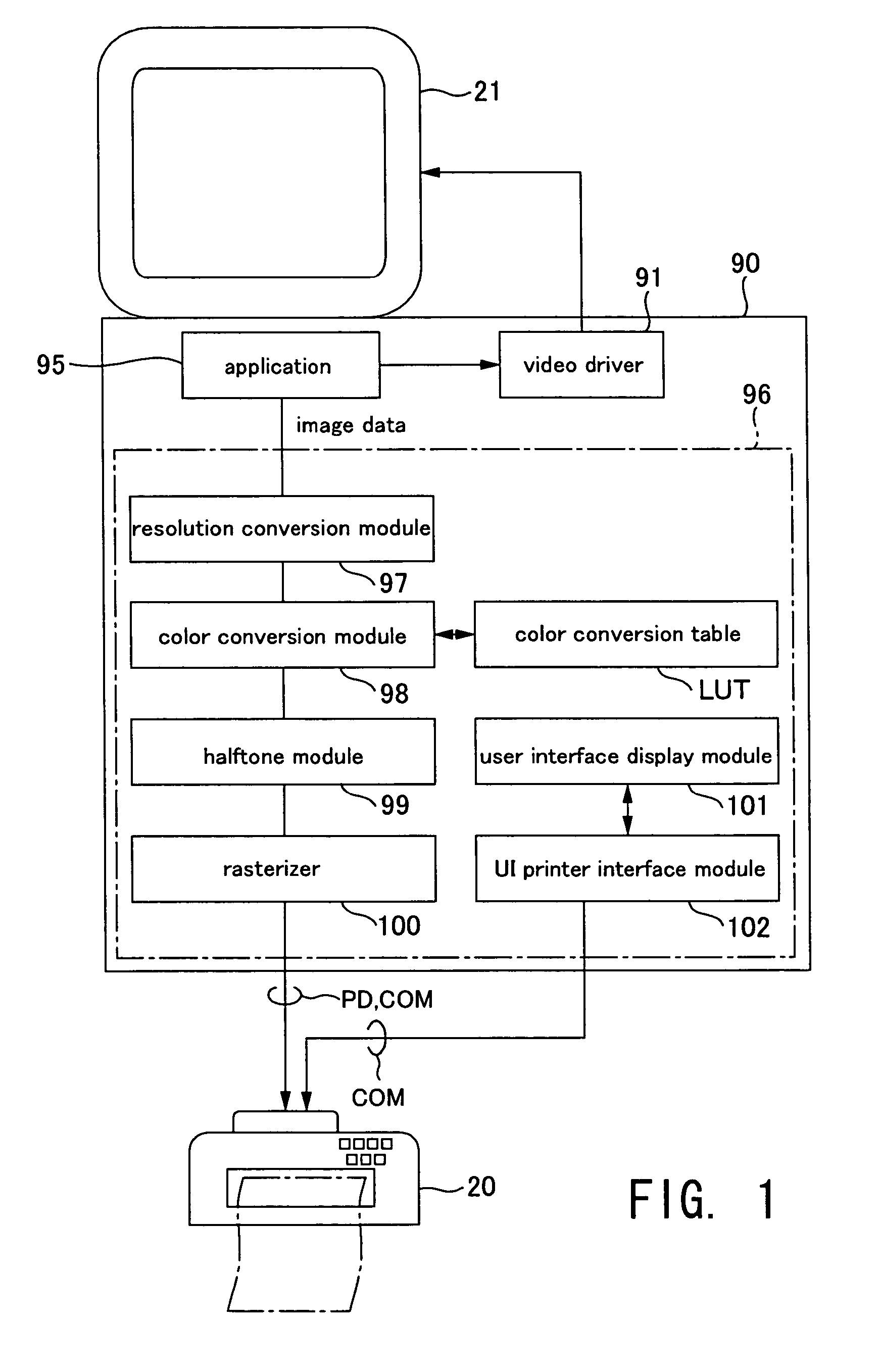
[0085]First, the user makes a command to perform printing through the application program 95 or the like (step S2). The application program 95 receives this instruction and issues a print command, at which time the printer driver 96 of the computer 90 receives image data from the application program 95 and converts them to print data PD including raster data indicating the state in which dots are formed during main scanning and data indicating the sub-scanning feed amount. Moreover, the printer driver 96 supplies the print data PD to the color inkjet printer 20 together with various commands COM. The color inkjet printer 20 receives these at its buff...


PUM


Abstract

A liquid ejection method of ejecting liquid from a movable ejection head onto a medium comprises the steps of: detecting a position of an end of the medium; and changing, according to a feed amount of the medium fed after the position of the end of the medium has been detected, at least either a starting position or a terminating position for ejecting the liquid from the ejection head being moved.

Description

CROSS-REFERENCE TO RELATED APPLICATIONS[0001]The present application claims priority upon Japanese Patent Application No. 2002-262975 filed Sep. 9, 2002, which is herein incorporated by reference.BACKGROUND OF THE INVENTION[0002]1. Field of the Invention[0003]The present invention relates to a liquid ejection method and a liquid ejecting apparatus.[0004]2. Description of the Related Art[0005]Color inkjet printers are already well known as representative liquid ejection apparatuses. These color ink-jet printers are provided with a print head, which is an example of an inkjet-type ejection head, for ejecting ink, which is an example of a liquid, from nozzles, and are configured so as to record images and characters, for example, by ejecting ink onto print paper, which is an example of a medium.[0006]The print head is supported on a carriage in a state with the nozzle face in which the nozzles are formed in opposition to the print paper, and is moved (in a main scan) in the width direc...

Claims


Application Information

Patent Timeline
IPC IPC(8): B41J29/393B41J2/01B41J11/00B41J19/18B41J29/38
CPCB41J11/008B41J11/0065
Inventor ENDO, HIRONORI
Owner SEIKO EPSON CORP
Why Eureka
Try Eureka