Control of a permanent-magnet motor

a permanent magnet, control technology, applied in the direction of synchronous motor starters, sport apparatus, vacuum cleaners, etc., can solve problems such as current spikes, and achieve the effects of less torque, smooth current waveform, and efficient motor

Active Publication Date: 2010-10-07
DYSON TECH LTD
View PDF56 Cites 42 Cited by
  • Summary
  • Abstract
  • Description
  • Claims
  • Application Information

AI Technical Summary

Benefits of technology

[0005]In the region of falling back emf, less torque is achieved for a given level of current. Accordingly, by freewheeling the winding within this region, a more efficient motor may be realised. Additionally, as the back emf in the winding falls, current spikes may arise should the excitation voltage exceed the falling back emf. By freewheeling the winding within the region of falling back emf, current spikes may be avoided and thus a smoother

Problems solved by technology

Additionally, as the back emf in the winding falls, current spikes

Method used


Image

  • Control of a permanent-magnet motor
  • Control of a permanent-magnet motor
  • Control of a permanent-magnet motor

Examples


Embodiment Construction

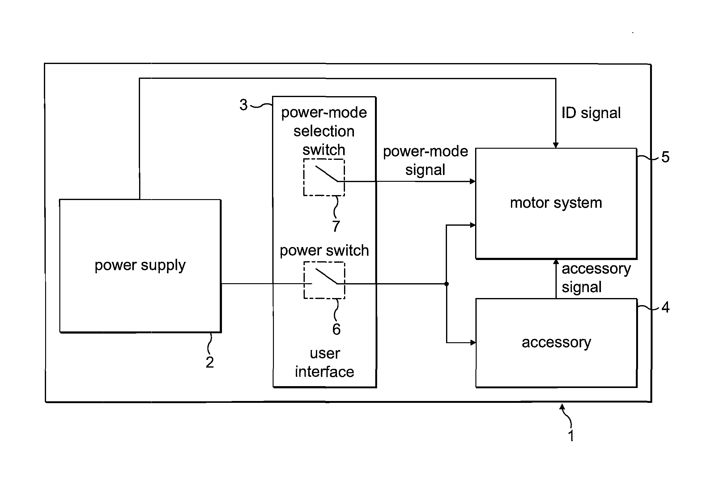
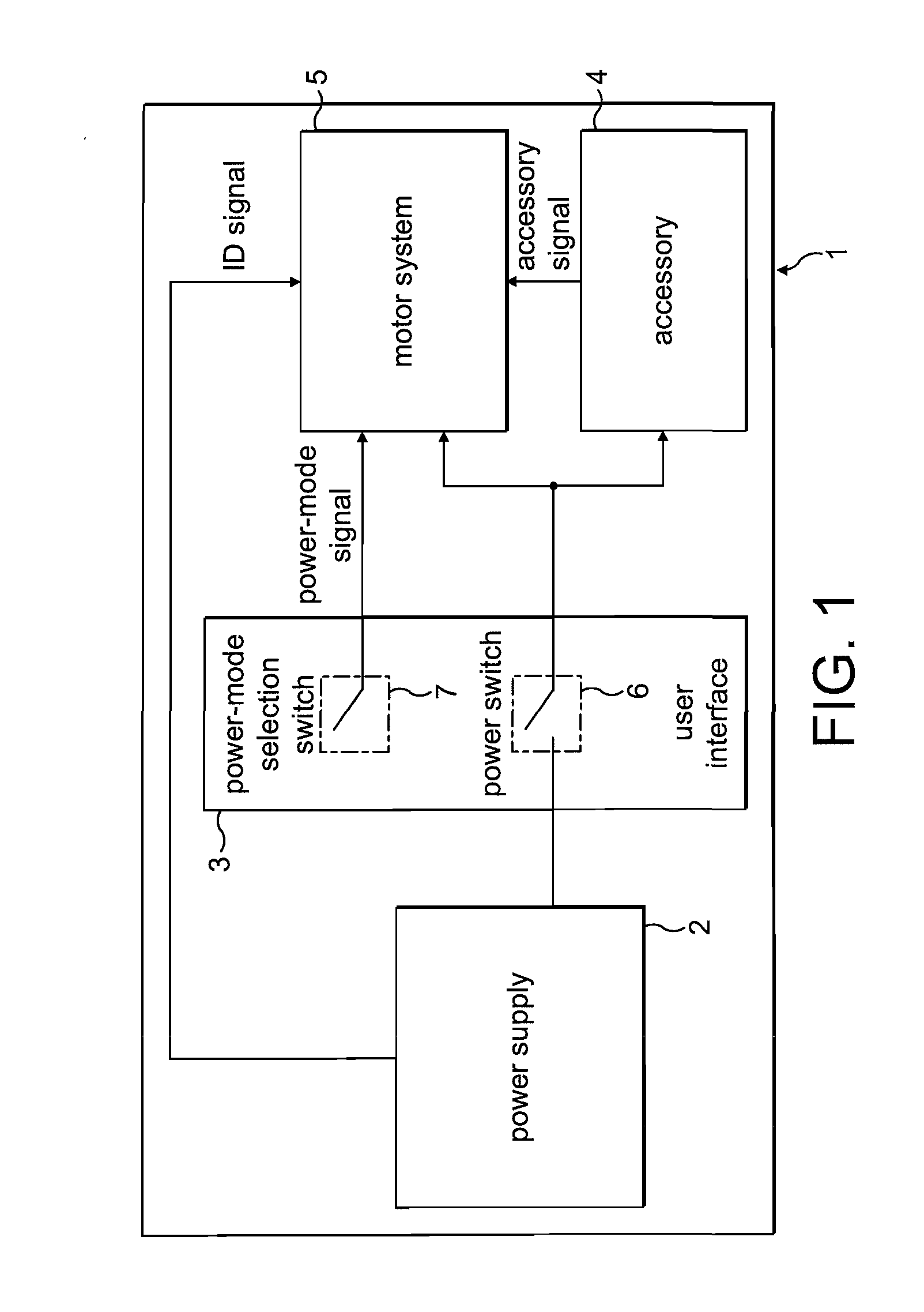
[0031]The product 1 of FIG. 1 comprises a power supply 2, a user interface 3, an accessory 4, and a motor system 5.

[0032]The power supply 2 comprises a battery pack that supplies a DC voltage to both the accessory 4 and the motor system 5. The power supply 2 is removable from the product 1 such that the product 1 may be used with different battery packs. For the purposes of the present description, the power supply 2 is either a 4-cell battery pack providing a 16.4 V DC supply or 6-cell battery pack providing a 24.6 V DC supply. In addition to providing a supply voltage, the power supply outputs an identification signal that is unique to the type of battery pack. The ID signal takes the form of a square-wave signal having a frequency that varies according to the type of battery pack. In the present example, the 4-cell battery pack outputs an ID signal having a frequency of 25 Hz (20 ms pulse length), while the 6-cell battery pack outputs an ID signal having a frequency of 50 Hz (10 ...


PUM


Abstract

A method of controlling a permanent-magnet motor that includes sequentially exciting and freewheeling a winding of the motor. The method includes varying the angle over which the winding is freewheeled in response to changes in speed of the motor. Additionally, a control system for a permanent-magnet motor, and a product incorporating the control system and motor.

Description

REFERENCE TO RELATED APPLICATIONS[0001]This application claims the priority of United Kingdom Application No. 0905920.5, filed Apr. 4, 2009, the entire contents of which are incorporated herein by reference.FIELD OF THE INVENTION[0002]The present invention relates to control of a permanent-magnet motor.BACKGROUND OF THE INVENTION[0003]As the rotor of a permanent-magnet motor rotates, it induces a back emf in a winding of the motor. As the rotor accelerates, the magnitude of the back emf increases. It therefore becomes increasingly difficult to drive current, and thus power, into the motor. As a result, control over the power of the motor becomes increasingly difficult.SUMMARY OF THE INVENTION[0004]In a first aspect, the present invention provides a method of controlling a permanent-magnet motor, the method comprising: sequentially exciting and freewheeling a winding of the motor, wherein the winding is freewheeled over a freewheel angle; and varying the freewheel angle in response t...

Claims


Application Information

Patent Timeline
IPC IPC(8): A47L9/22H02P6/08H02P27/08
CPCA47L5/24A47L9/0411A47L9/2831A47L9/2847A47L9/2884Y02B40/82H02P6/008H02P6/085H02P6/145H02P29/026A47L9/2889H02P6/153H02P6/26Y02B40/00H02K21/12H02K29/08H02P6/15
Inventor CLOTHIER, ANDREW CHARLTONCELIK, TUNCAYCHEN, YU
Owner DYSON TECH LTD
Why Eureka
Try Eureka