Microneedle cartridge assembly and method of applying

a technology of microneedle and cartridge, which is applied in the field of microneedle array cartridges, can solve the problems of large space occupation, large amount of bulky structures, and fragile and sanitary characteristics, and achieve the effects of time-consuming and difficult for operators, fragile and sanitary characteristics, and large space occupation

Inactive Publication Date: 2010-10-07
3M INNOVATIVE PROPERTIES CO
View PDF89 Cites 76 Cited by
  • Summary
  • Abstract
  • Description
  • Claims
  • Application Information

AI Technical Summary

Benefits of technology

[0007]Patches, with or without a microneedle array, can have fragile and sanitary characteristics. It is generally desired that the patch and array not be contacted before application to a target site. This presents difficulties in storing and transporting patches to desired locations for eventual application. In addition, providing collars or other protection for mic

Problems solved by technology

Patches, with or without a microneedle array, can have fragile and sanitary characteristics.
This presents difficulties in storing and transporting patches to desired locations for eventual application.
In addition, providing collars or other protection for microneedle array

Method used


Image

  • Microneedle cartridge assembly and method of applying
  • Microneedle cartridge assembly and method of applying
  • Microneedle cartridge assembly and method of applying

Examples


first embodiment

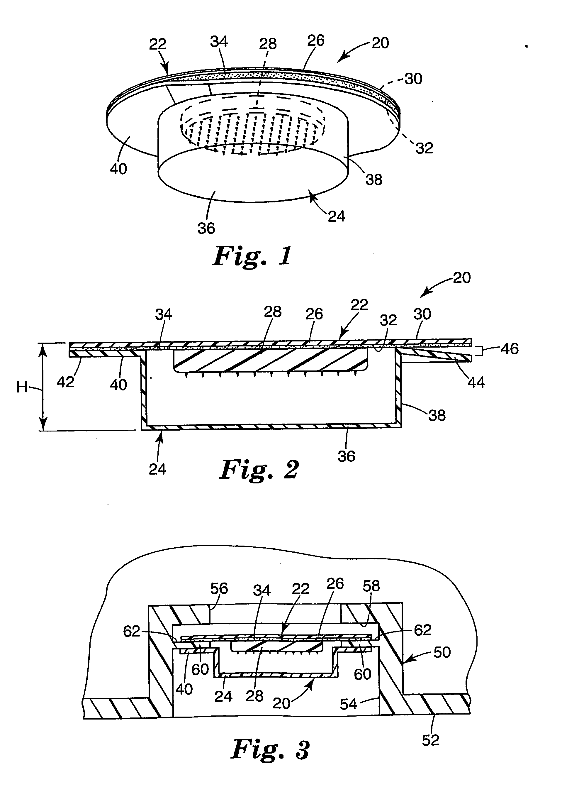
[0034]FIG. 1 is a perspective view of a microneedle cartridge 20 that includes a patch 22 and a container 24. FIG. 2 is a cross-sectional view of the microneedle cartridge 20. The patch 22 shown in FIGS. 1 and 2 includes a web of material 26 that forms a backing, and a microneedle array 28 supported by and attached to the web of material 26. The web of material 26 is generally flat, and has an upper face 30 and a lower face 32. The web of material 26 can be comprised of a polymeric film, cloth, nonwoven or the like. An adhesive 34, such as a pressure sensitive adhesive, is disposed on the lower face 32 of the web of material 26. The microneedle array 28 is located relative to the lower face 32 of the web of material 26 at a generally central portion of the web of material 26, which has a circular shape. The microneedle array 28 can be attached to the web of material 26, for example, by adhesive, welding, heat bonding, and can be formed integrally with the web of material 26.

[0035]Su...

second embodiment

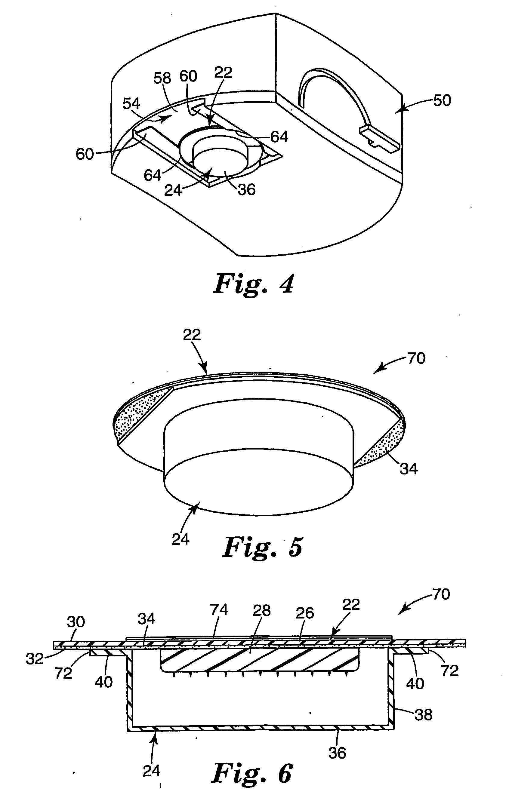
[0048]FIGS. 5-8 show a microneedle cartridge 70. FIG. 5 is a perspective view of the microneedle cartridge 70. FIG. 6 is a front cross-sectional view of the microneedle cartridge 70, and FIG. 7 is a side cross-sectional view of the microneedle cartridge 70. FIG. 8 is a bottom view of the microneedle cartridge 70.

[0049]The microneedle cartridge 70 includes a patch 22 and a container 24. The patch 22 includes a web of material 26, a microneedle array 28 and an adhesive 34 on a bottom face 32 of the web of material 26, and is generally similar to that shown and described with respect to FIGS. 1-4 above. The container 24 is removably attached to the patch 22 to cover the microneedle array 28. The container 24 includes a circular central base portion 36, a sidewall 38 connected at or near the perimeter of the central base portion 36, and a perimeter lip 40 connected to the sidewall 38 opposite the central base portion 36. A pair of opposed cutouts 72 are provided in the perimeter lip 40....

third embodiment

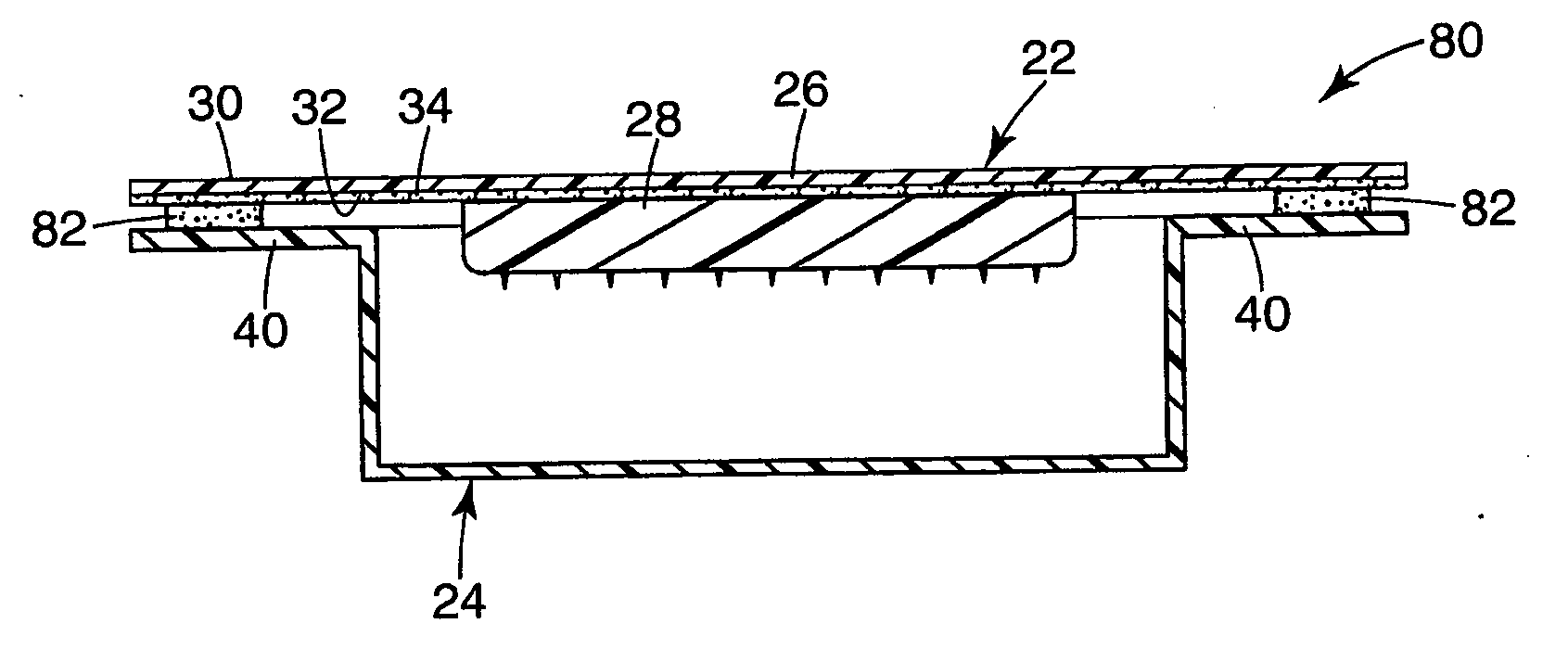
[0051]FIG. 9 is a perspective view of a microneedle cartridge 80. FIG. 10 is a cross-sectional view of the microneedle cartridge 80. As shown in FIGS. 9 and 10, the microneedle cartridge 80 includes a patch 22 and a container 24. The patch 22 includes a web of material 26, a microneedle array 28 and an adhesive 34 on a bottom face 32 of the web of material 26, and is generally similar to those shown and described with respect to FIGS. 1-8 above. The container is removably attached to the patch 22 to cover the microneedle array 28. The container 24 includes a circular central base portion 36, a sidewall 38 connected at or near the perimeter of the central base portion 36, and a perimeter lip 40 connected to the sidewall 38 opposite the central base portion 36. A gasket 82 is disposed to adhere to the lip 40 of the container 24 and patch (i.e., to the web of material 26 or the adhesive 34). The gasket 82 is disposed in a substantially continuous band around the microneedle array 28 in...


PUM


Abstract

A microneedle array cartridge includes a web of material having a top face and an opposite bottom face. An adhesive and a microneedle array are disposed on the bottom face of the web of material. A container is disposed relative to the bottom face of the web of material, and has a perimeter portion and a central portion for covering at least part of the microneedle array. At least part of the perimeter portion of the container contacts the adhesive, and the central portion of the container does not contact the adhesive. The perimeter portion and the central portion of the container are integrally formed.

Description

CROSS-REFERENCE TO RELATED APPLICATIONS[0001]The present application claims priority to U.S. Provisional Application Ser. No. 60 / 694,446, filed on Jun. 27, 2005, which is incorporated herein in its entirety.FIELD[0002]The present invention relates to microneedle array cartridges.BACKGROUND[0003]Only a limited number of molecules with demonstrated therapeutic value can be transported through the skin via unassisted or passive transdermal drug delivery. The main barrier to transport of molecules through the skin is the stratum corneum (the outermost layer of the skin).[0004]Devices including arrays of relatively small structures, sometimes referred to as microneedles or micro-pins, have been disclosed for use in connection with the delivery of therapeutic agents and other substances through the skin and other surfaces. The devices are typically pressed against the skin in an effort to pierce the stratum corneum. The microneedle arrays are generally used once and then discarded.[0005]M...

Claims


Application Information

Patent Timeline
IPC IPC(8): A61M5/00
CPCA61M2037/0023A61M37/0015
Inventor FREDERICKSON, FRANKLYN L.JOHNSON, MICHAEL D.
Owner 3M INNOVATIVE PROPERTIES CO
Why Eureka
Try Eureka