
Device including moveable portion for controlling fluid

Inactive Publication Date: 2010-10-14
EASTMAN KODAK CO
View PDF2 Cites 3 Cited by
  • Summary
  • Abstract
  • Description
  • Claims
  • Application Information

AI Technical Summary

Benefits of technology

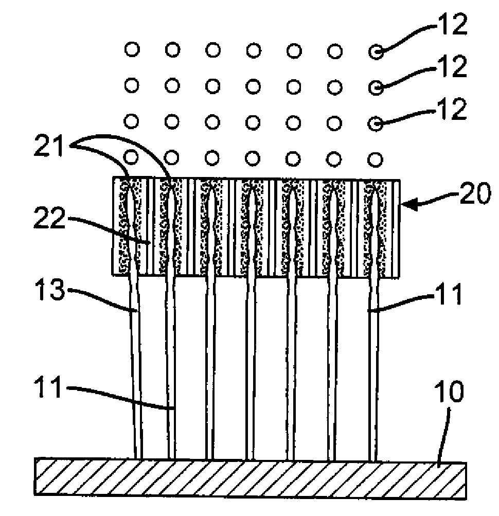
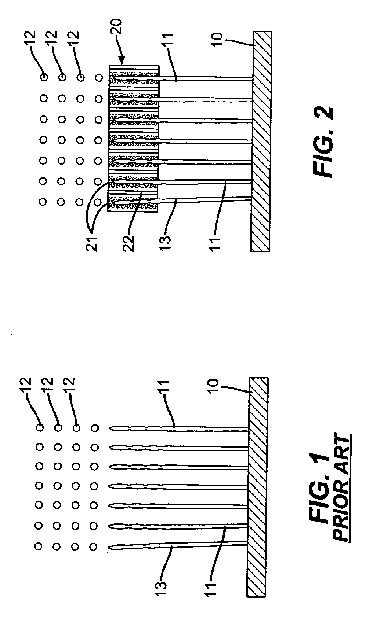
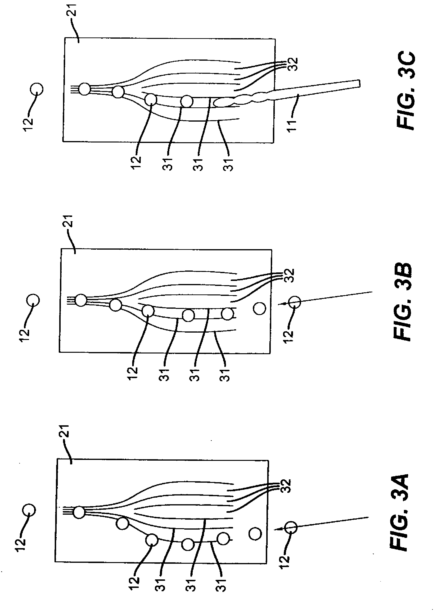
[0011]The control device of the present invention also has the ability to selectively suppress satellite drops and to reduce inadvertent drop merger. For example, the control surface of the control device can be designed to passively or actively control (modulate) the trajectory and velocity of the exiting drops relative to the that of the incoming drops on a drop by drop basis so as to cause satellite drops to merge with other drops or prevent drops from inadvertently merging with each other.

Problems solved by technology

Accurate positioning of drops on the receiver is difficult because ejected drops suffer from both stochastic (random) placement inaccuracies and repeating (semi-permanent) placement inaccuracies.
However, overly close spacing may cause mechanical contact between the printhead and the receiver possibly resulting in printhead damage.
However, these strategies need to use very large airflows or very high electric fields to influence drop trajectories which possibly resulting in image artifacts and reduced system reliability.
Accurate positioning of drops on the receiver is also limited by the formation of satellite drops during drop breakup or by drop recombination as drops travel along their trajectories.
Drops of unusually small or large sizes are produced which reduce image quality or cause reliability problems due to fluid accumulation at unwanted regions.
Although satellite formation can be controlled to some extent by ink formulation or printhead operation parameters, these solutions typically reduce image quality or printer performance, for example by requiring special ink formulations not optimized for image quality or by necessitation reduced printing speeds.
However, drop placement typically suffers at high frequency operation while the propensity of satellite formation or drop recombination typically increases.

Method used


Image

  • Device including moveable portion for controlling fluid
  • Device including moveable portion for controlling fluid
  • Device including moveable portion for controlling fluid

Examples


Embodiment Construction

[0034]The present description will be directed in particular to elements forming part of, or cooperating more directly with, apparatus in accordance with the present invention. It is to be understood that elements not specifically shown or described may take various forms well known to those skilled in the art. In the following description and drawings, identical reference numerals have been used, where possible, to designate identical elements.

[0035]The example embodiments of the present invention are illustrated schematically and not to scale for the sake of clarity. One of the ordinary skills in the art will be able to readily determine the specific size and interconnections of the elements of the example embodiments of the present invention.

[0036]As described herein, the example embodiments of the present invention provide a printhead or printhead components typically used in inkjet printing systems. However, many other applications are emerging which use inkjet printheads to em...


PUM


Abstract

A device and a method of controlling fluid flow are provided. The method includes providing a moving fluid including a fluid flow characteristic; providing a fluid control device including a fluid control surface, a portion of the fluid control surface being moveable; causing the fluid to contact the fluid control surface of the fluid control device; and causing the fluid to interact with the fluid control surface of the fluid control device by moving the moveable portion of the fluid control surface while the fluid is in contact with the fluid control surface such that the fluid flow characteristic of the fluid after interacting with the fluid control surface of the fluid control device is different from the fluid flow characteristic of the fluid before interaction with the fluid control surface of the fluid control device depending on the position of the moveable portion of the fluid control surface.

Description

CROSS REFERENCE TO RELATED APPLICATIONS[0001]Reference is made to commonly-assigned, U.S. patent application Ser. No. ______ (Docket 95586), entitled “DEVICE FOR CONTROLLING FLUID VELOCITY”, Ser. No. ______ (95584), entitled “DEVICE FOR CONTROLLING DIRECTION OF FLUID”, Ser. No. ______ (Docket 95585), entitled “INTERACTION OF DEVICE AND FLUID USING FORCE ”, and Ser. No. ______ (Docket 95587), entitled “DEVICE FOR MERGING FLUID DROPS OR JETS”, all filed concurrently herewith.FIELD OF THE INVENTION[0002]This invention relates generally to formation and control of fluid drops, and in particular to control devices that either actively or passively control fluid drops via interaction of a fluid jet and a control device surface at or near the region of fluid jet breakoff.BACKGROUND OF THE INVENTION[0003]The ability to reliably and accurately position drops ejected from fluid ejectors, for example, inkjet printheads, at predetermined locations is a critical systems requirement for the print...

Claims


Application Information

Patent Timeline
IPC IPC(8): F17D3/00
CPCF17D1/14Y10T137/0324Y10T137/7837
Inventor HAWKINS, GILBERT A.GAO, ZHANJUNXIE, YONGLINFURLANI, EDWARD P.NG, KAM C.
Owner EASTMAN KODAK CO
Features
  • Generate Ideas
  • Intellectual Property
  • Life Sciences
  • Materials
  • Tech Scout
  • Unparalleled Data Quality
  • Higher Quality Content
  • 60% Fewer Hallucinations
Learn More