Display device

a display device and display technology, applied in the field of display devices, can solve the problems of slow rate, image quality degradation, and difficulty in immediately providing display devices with the larger area, and achieve the effect of light weight and simple structur

Active Publication Date: 2010-10-14
SHARP KK
View PDF8 Cites 81 Cited by
  • Summary
  • Abstract
  • Description
  • Claims
  • Application Information

AI Technical Summary

Benefits of technology

[0028]According to the present invention, there is provided a display device in which a frame region of a display panel, or a joint in the case of tiling, is unlikely to be seen, with a structure which is more simple and light-weighted than conventionally. Moreover, according to the present invention, by merely placing an appropriately designed Fresnel lens plate at a predetermined position of an existing display panel or display unit (composed of a display panel and the like accommodated in a housing), a frame region of a display panel, or a joint in the case of tiling, can be made unlikely to be seen.

Problems solved by technology

Representative examples of large-sized display devices are display devices in which self-emission elements such as light-emitting diodes (LEDs) are arranged in a matrix array and projection display devices; however, these have disadvantages in terms of image quality.
The substrates that are available for mass production will become more increased in size, however at a slow rate.
It is difficult to immediately provide display devices with the larger areas that are required on the current market.
However, the tiling technique induces a problem of visible joints between the plurality of display devices.

Method used


Image

  • Display device
  • Display device
  • Display device

Examples


Embodiment Construction

[0056]Hereinafter, an embodiment of the present invention will be described with reference to the drawings. However, the present invention is not limited to the illustrated embodiment.

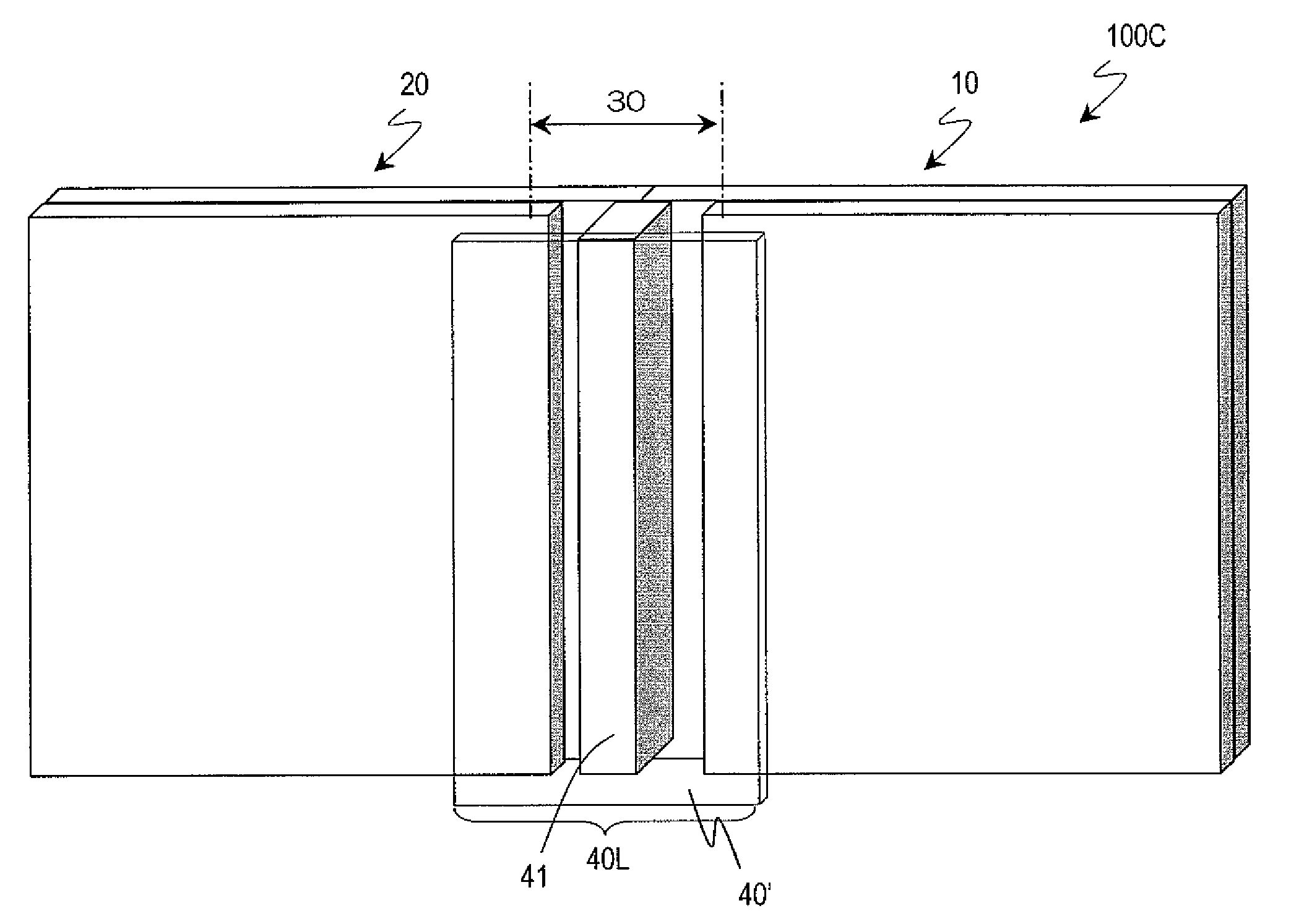
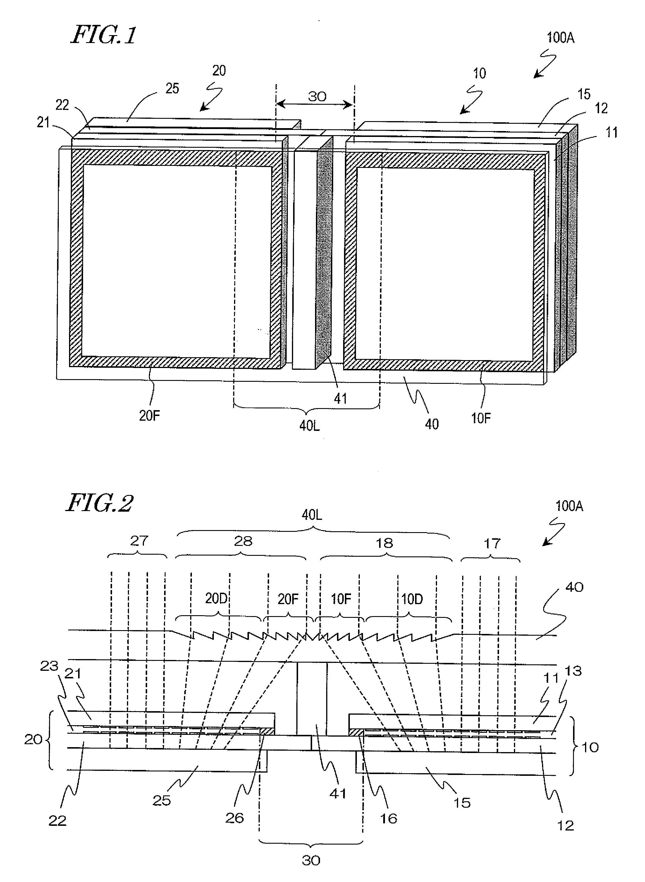
[0057]FIG. 1 and FIG. 2 schematically show a direct-viewing type display device 100A according to an embodiment of the present invention. FIG. 1 is a schematic perspective view of the display device 100A as seen from the viewer side. FIG. 2 is a schematic cross-sectional view of the display device 100A, where the upper side in the figure corresponds to the viewer side. Although a liquid crystal display device in which a liquid crystal display panel is used as the display panel will be illustrated below, this is not a limitation; a display panel for PDP, an organic EL display panel, or an electrophoresis display panel can be used.

[0058]The liquid crystal display device 100A includes two liquid crystal display panels 10 and 20. The liquid crystal display panels 10 and 20 each have a display region and a ...


PUM


Abstract

A direct-viewing type display device according to the present invention includes: at least one display panel having a display region and a frame region formed outside of the display region; and at least one Fresnel lens plate disposed on a viewer side of the at least one display panel with a predetermined interval therefrom. The Fresnel lens plate includes a Fresnel lens region at a position overlapping a region that contains a portion of the frame region of the display panel and a portion of a peripheral display region within the display region that adjoins the portion of the frame region along a first axis. A portion of display light exiting the portion of the peripheral display region is emitted from a region of the Fresnel lens region that overlaps a portion of the frame region, or a region outside the region, toward the viewer side. According to the present invention, there is provided a direct-viewing type display device in which a frame region of a display panel, or a joint in the case of tiling, is made unlikely to be seen, with a structure which is more simple and light-weighted than conventionally.

Description

TECHNICAL FIELD[0001]The present invention relates to a display device, and in particular to a direct-viewing type display device.BACKGROUND ART[0002]In recent years, there is a strong desire for an increase in the size of television sets and display devices for displaying information. Representative examples of large-sized display devices are display devices in which self-emission elements such as light-emitting diodes (LEDs) are arranged in a matrix array and projection display devices; however, these have disadvantages in terms of image quality. Therefore, a further increase in the size of direct-viewing type liquid crystal display devices (LCDs) and plasma display devices (PDPs), which are capable of displaying with a high image quality, is being desired.[0003]Since a direct-viewing type liquid crystal display device or a plasma display device is basically formed on a glass substrate, its screen size depends on the substrate size. Currently, the largest of glass substrates (moth...

Claims


Application Information

Patent Timeline
Patent Type & Authority Applications(United States)
IPC IPC(8): G09G5/14G09G5/10G02B3/08
CPCG02B3/08G02B27/1066G02B27/123G02B27/126G02F1/13336G09G2340/0407G09G3/20G09G3/342G09G3/3611G09G2300/026G09G2320/0233G02F1/133526
Inventor WATANABE, HISASHI
Owner SHARP KK
Why Eureka
Try Eureka