Culinary Utensil

a technology for cooking utensils and utensils, which is applied in the field of man-made culinary utensils, can solve the problems that the cutting blade cannot be easily broken off the skin of the food surface, and achieve the effect of more predictable and reliable cutting and optimal cutting interaction

Inactive Publication Date: 2010-10-21
MAXPAT TRADING & MARKETING FAR EAST LTD
View PDF25 Cites 11 Cited by
  • Summary
  • Abstract
  • Description
  • Claims
  • Application Information

AI Technical Summary

Benefits of technology

[0005]Preferably, the two taller teeth which are adjacent to each other may be separated by three to five shorter teeth on the cutting edge. The use of three to five shorter teeth for it can provide an optimal cutting interaction with the food to be cut. If there were too many shorter teeth between the two adjacent taller teeth the cutting edge would not readily slice into the food after the skin surface of the food is bitten into by the taller teeth, and if there were too few teeth between the adjacent taller teeth the cutting blade would not be able to break the skin of the food surface readily. While the use of three to five shorter teeth is optimal, the use of three to eight shorter teeth is still found to be satisfactory. Advantageously, the taller teeth along the blade may be evenly spaced so that a more predictable and reliable cutting can be achieved.

Problems solved by technology

If there were too many shorter teeth between the two adjacent taller teeth the cutting edge would not readily slice into the food after the skin surface of the food is bitten into by the taller teeth, and if there were too few teeth between the adjacent taller teeth the cutting blade would not be able to break the skin of the food surface readily.

Method used


Image

  • Culinary Utensil
  • Culinary Utensil
  • Culinary Utensil

Examples


first embodiment

[0022]a culinary utensil according to the present invention is one which comprises a cutting blade as described above or one which fits the description of the variations.

second embodiment

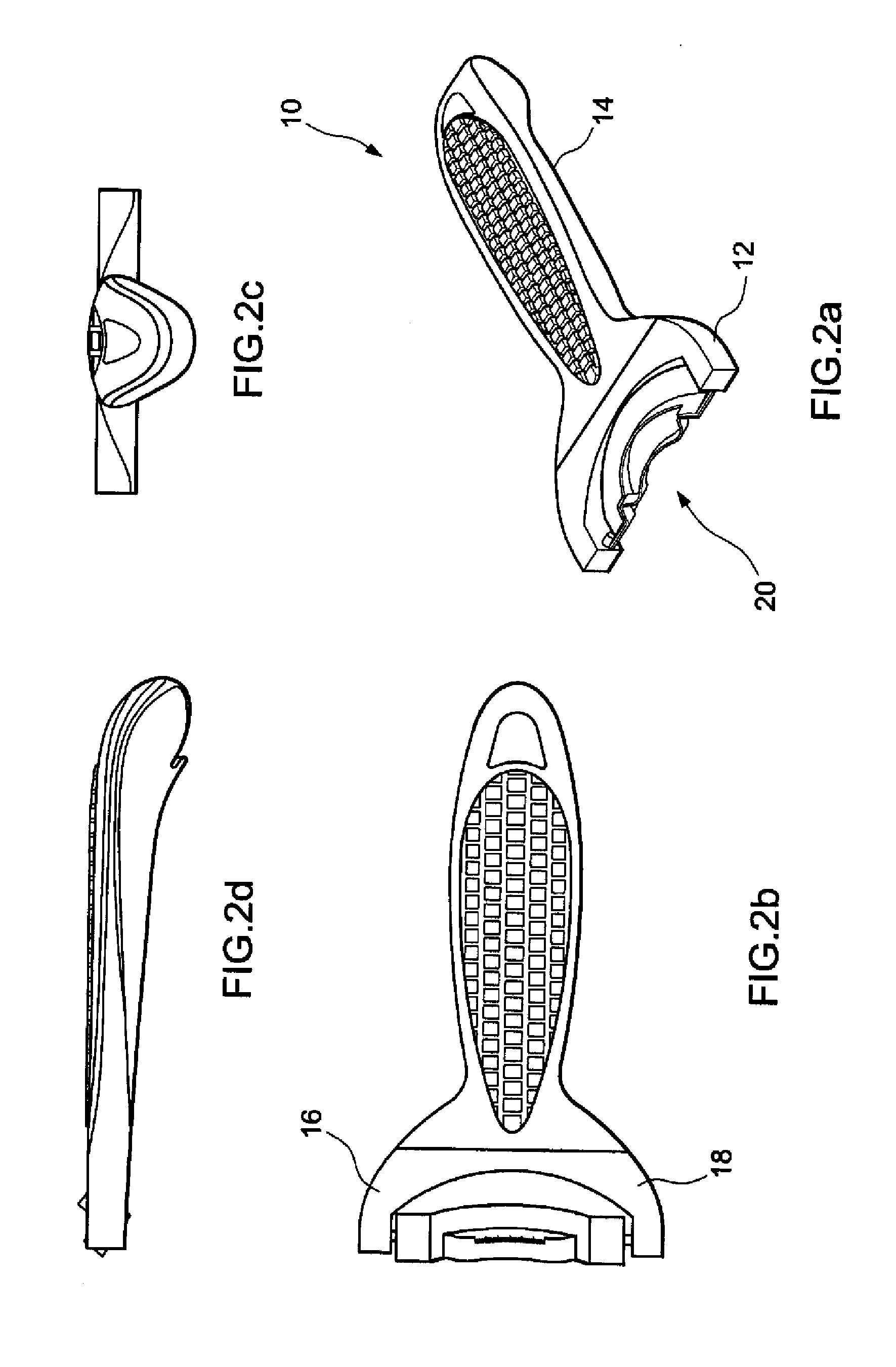
[0023]a culinary utensil 10 according to the present invention takes the form of a corn scraper 10 for removing kernels from an ear of corn and is illustrated in FIGS. 2a to 3c. FIGS. 2a to 2d are artistic diagrams showing the corn scraper's appearance. The corn scraper 10 comprises a utility portion 12 and a handle portion having an elongate handle 14 defining an axis extending from the front end of the utensil to the rear end of the utensil 10. The handle 14 is sized and shaped to fit the grip of a hand of a user in use. The front end of the handle 14 forks off to two legs 16, 18 generally resembling the letter “U” and defining the utility portion 12. Between the legs there is provided with a cutting structure 20 for scraping the corn.

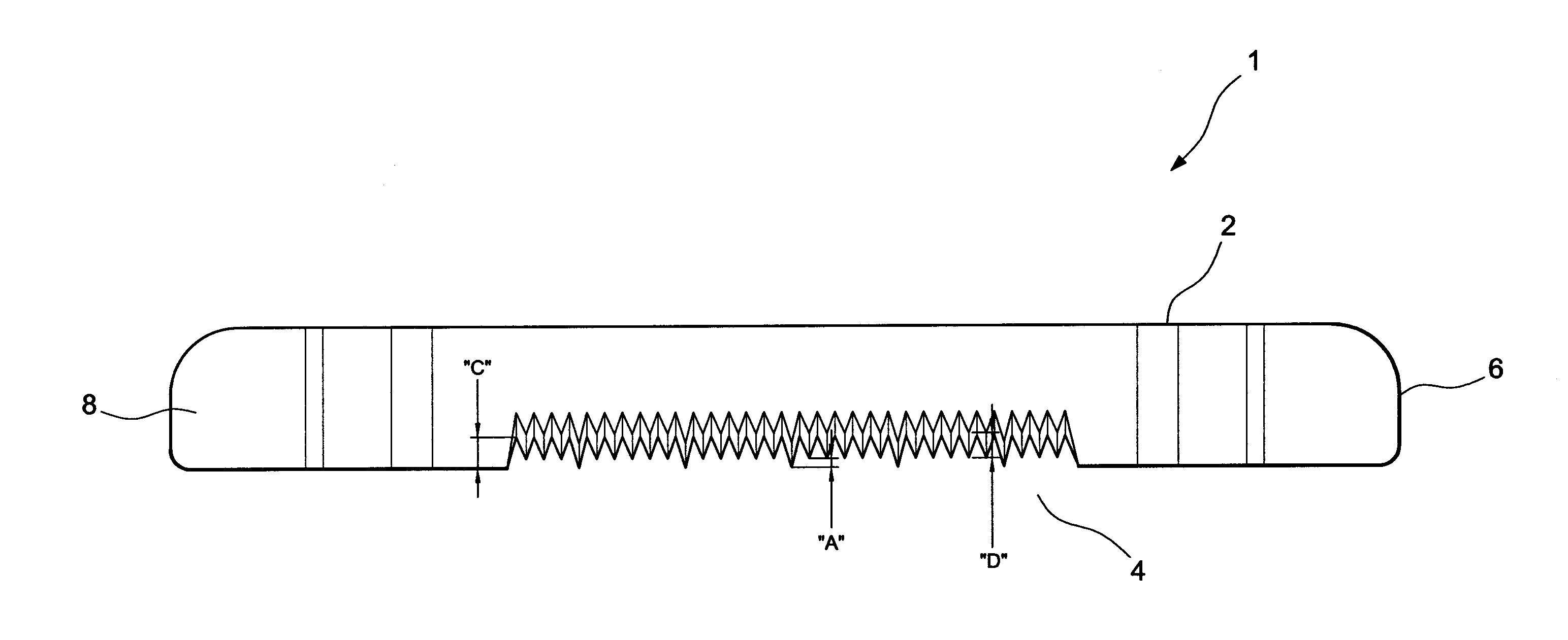
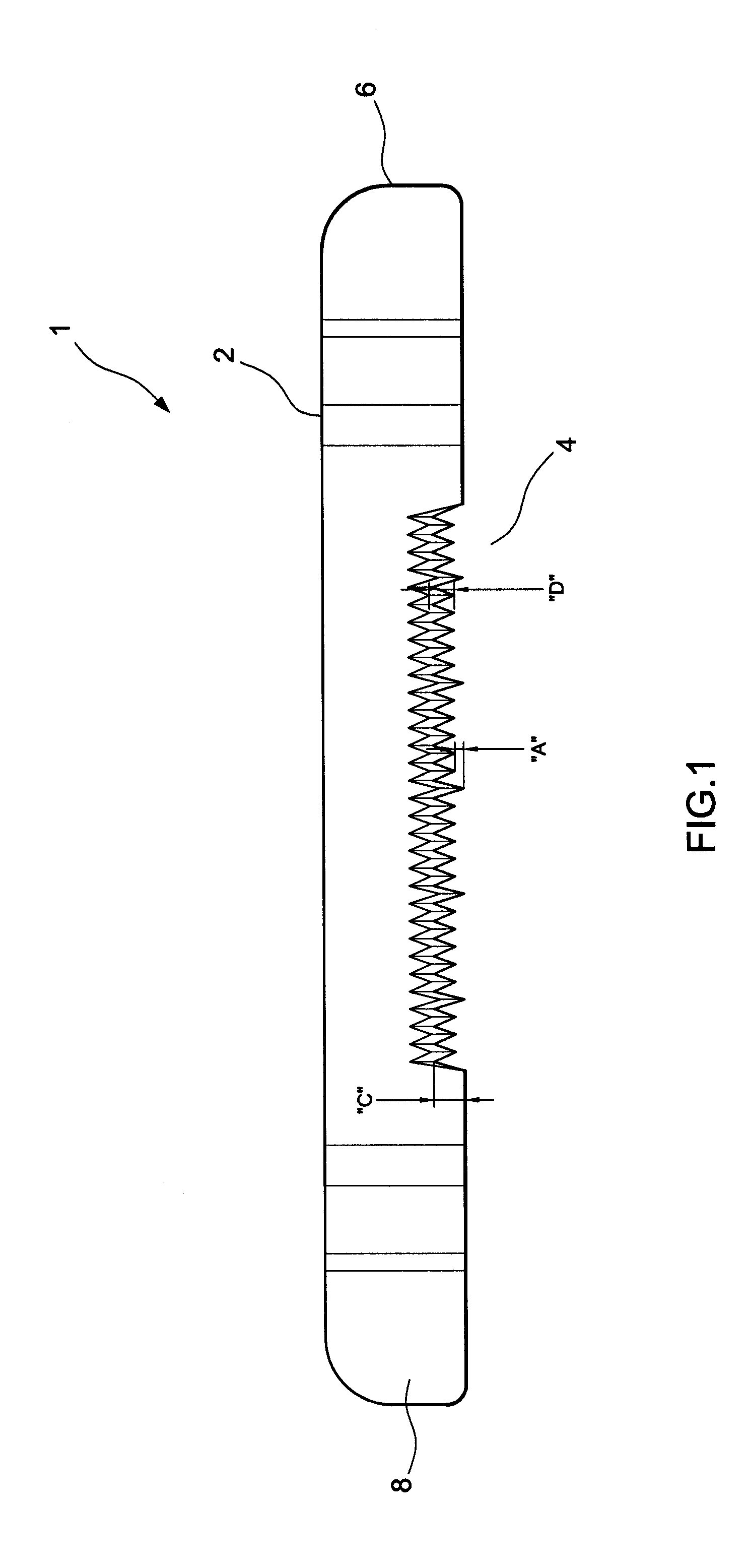
[0024]The cutting structure 20 includes a cutting blade 22 generally as described above and as illustrated in FIG. 1. Since this culinary utensil 10 is for scraping corn, the blade 22 is additionally configured with a curved profile, with the curvatu...

third embodiment

[0027]FIGS. 4a to 4d illustrate a culinary utensil according to the present invention in which the culinary utensil takes the form of a food slicer 30. The food slicer 30 has a cylindrical casing 32 with an upper opening 34 and a lower opening 36. In this embodiment, the casing 32 is made of stainless steel although other suitable durable material may be used. On lateral opposite sides of the casing 32 there is a pair of handles 38, 40 extending at the top therefrom. The slicer 30 is provided with a plurality of planar cutting blades 1 as described above in FIG. 1. The cutting blades 1 are arranged in parallel and are fixedly secured within and at a lower end of the casing 32 with the cutting edge pointing downwardly. In use, when the food slicer is used, for example, to slice a tomato, a user will hold the slicer 30 on the handles 38, 40 with his hands and place the slicer 30 above the tomato. Then, the slicer 30 is lowered and pressed down onto the tomato until the cutting edge 4 ...


PUM


Abstract

There is provided a culinary utensil comprising a blade provided with a cutting edge on at least one side thereof, said cutting edge is formed of at least one set of taller teeth and one set of shorter teeth, wherein at least two adjacent taller teeth are separated by three to eight shorter teeth on the cutting edge.

Description

FIELD OF THE INVENTION[0001]The present invention is concerned with a manual culinary utensil provided with a specially designed cutting blade mainly for cutting fruits and vegetables. The present invention is concerned with such culinary utensil but not limited to corn scraper, tomato slicer, egg slicer, and fruit or vegetable core remover or wedger.BACKGROUND OF THE INVENTION[0002]There are a variety of culinary utensils for processing food or for cooking purposes. Processing for example fruits and vegetables before cooking often involves cutting, peeling and / or scraping. Many conventional culinary utensils are usually equipped with a sharp blade for cutting or peeling but despite the sharp blade these culinary utensils are not always satisfactory in their performance.[0003]The present invention seeks to address this problem or at the least to provide an alternative to the public.SUMMARY OF THE INVENTION[0004]According to one aspect of the present invention, there is provided a cu...

Claims


Application Information

Patent Timeline
Patent Type & Authority Applications(United States)
IPC IPC(8): A47J17/02B26B9/02A47J25/00
CPCA47J25/00A47J43/25B26B9/02B26D2001/006B26D1/553B26D3/26B26D2001/0033B26D1/0006A47J17/02B26B3/04
Inventor SETTELE, IGNAZHAUTLE, SABINE
Owner MAXPAT TRADING & MARKETING FAR EAST LTD
Why Eureka
Try Eureka