
Aircraft main engine fuel pump with multiple gear stages using shared journals
a fuel pump and gear stage technology, applied in the direction of liquid fuel engines, machines/engines, rotary piston liquid engines, etc., can solve the problems of premature wear of journal bearings, gear tooth failure, and first pump inclination to become unstable, so as to reduce the possibility of bearing oil whirl, limit premature wear, and minimize energy consumption
- Summary
- Abstract
- Description
- Claims
- Application Information
AI Technical Summary
Benefits of technology
Problems solved by technology
Method used
Image

Examples
Embodiment Construction
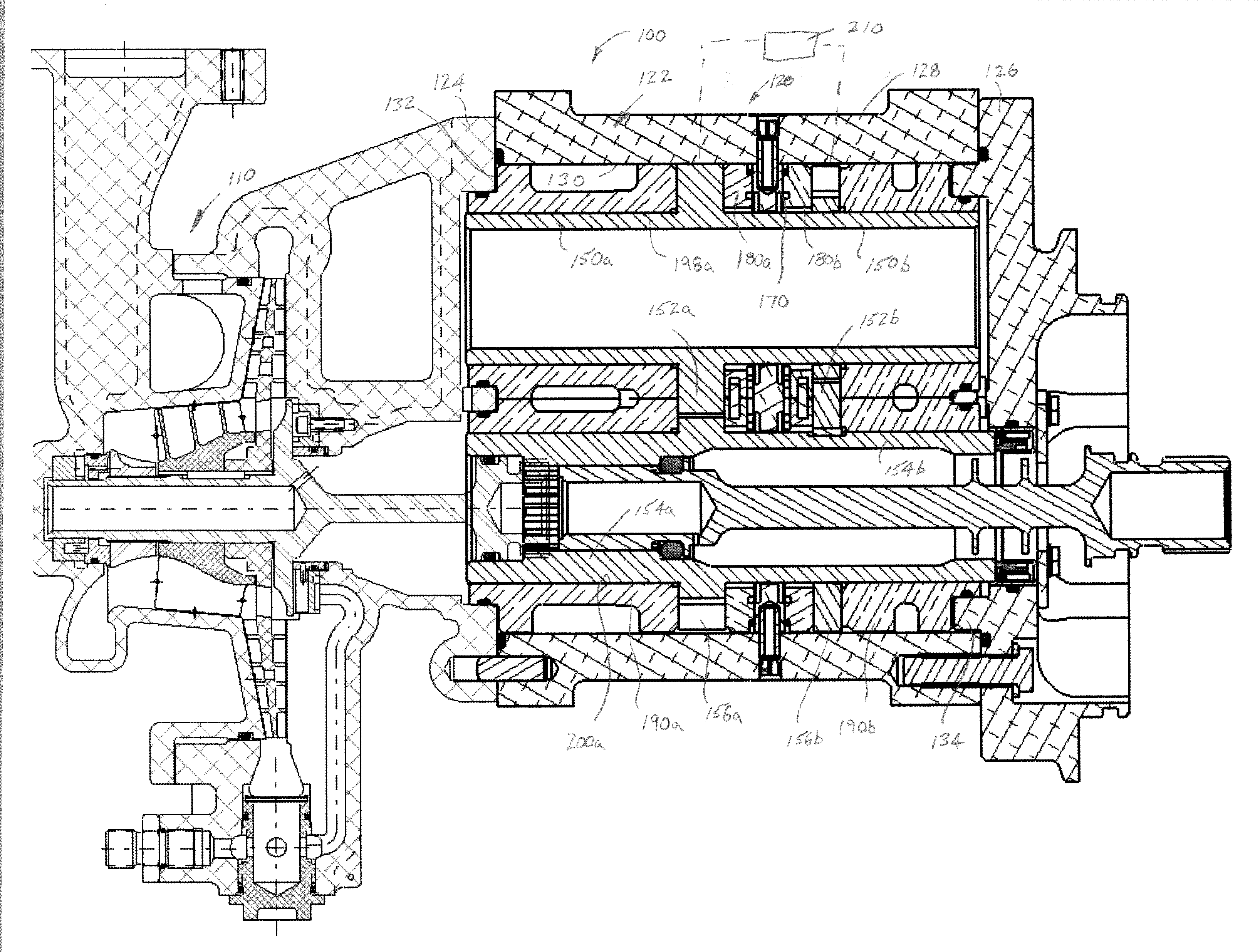
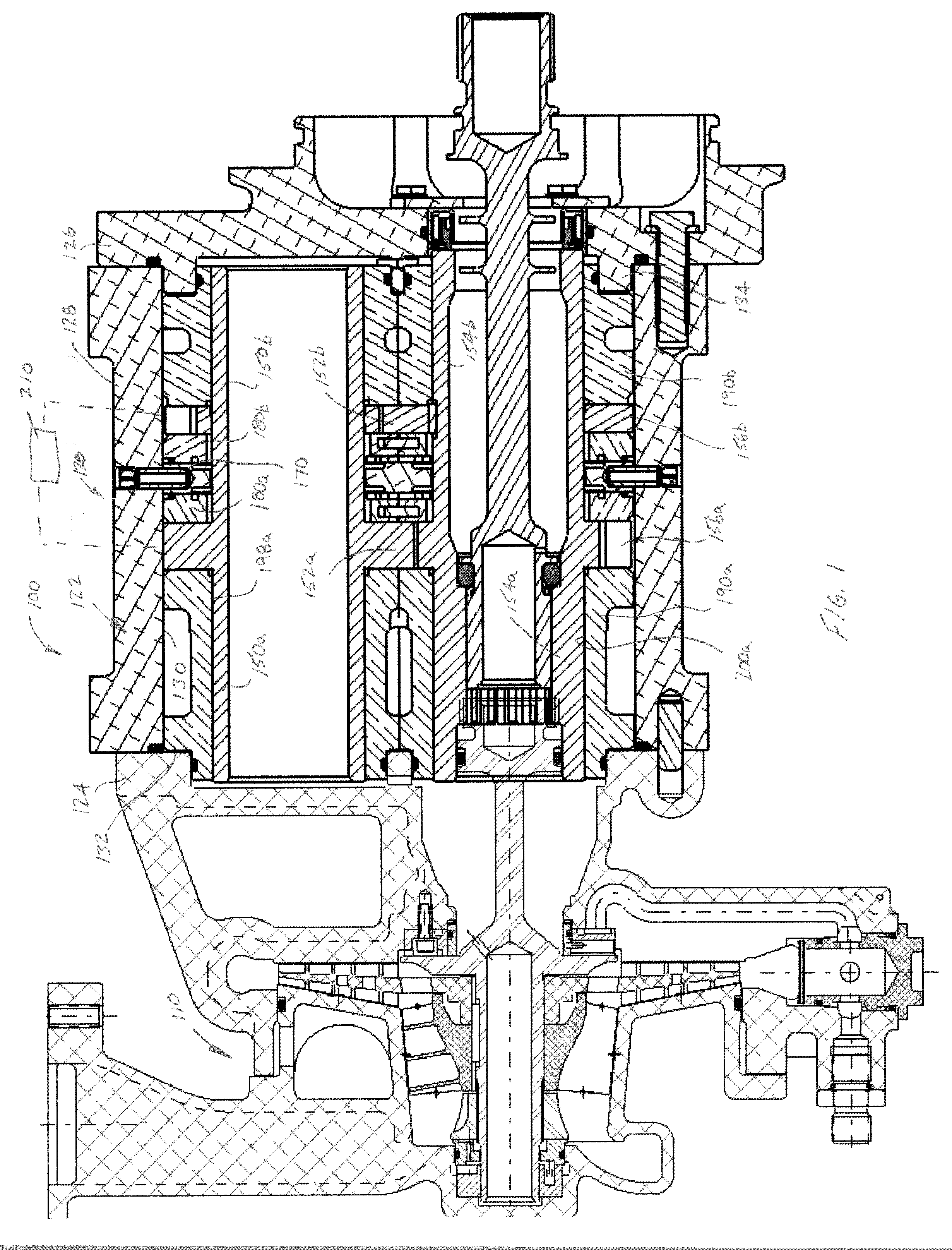
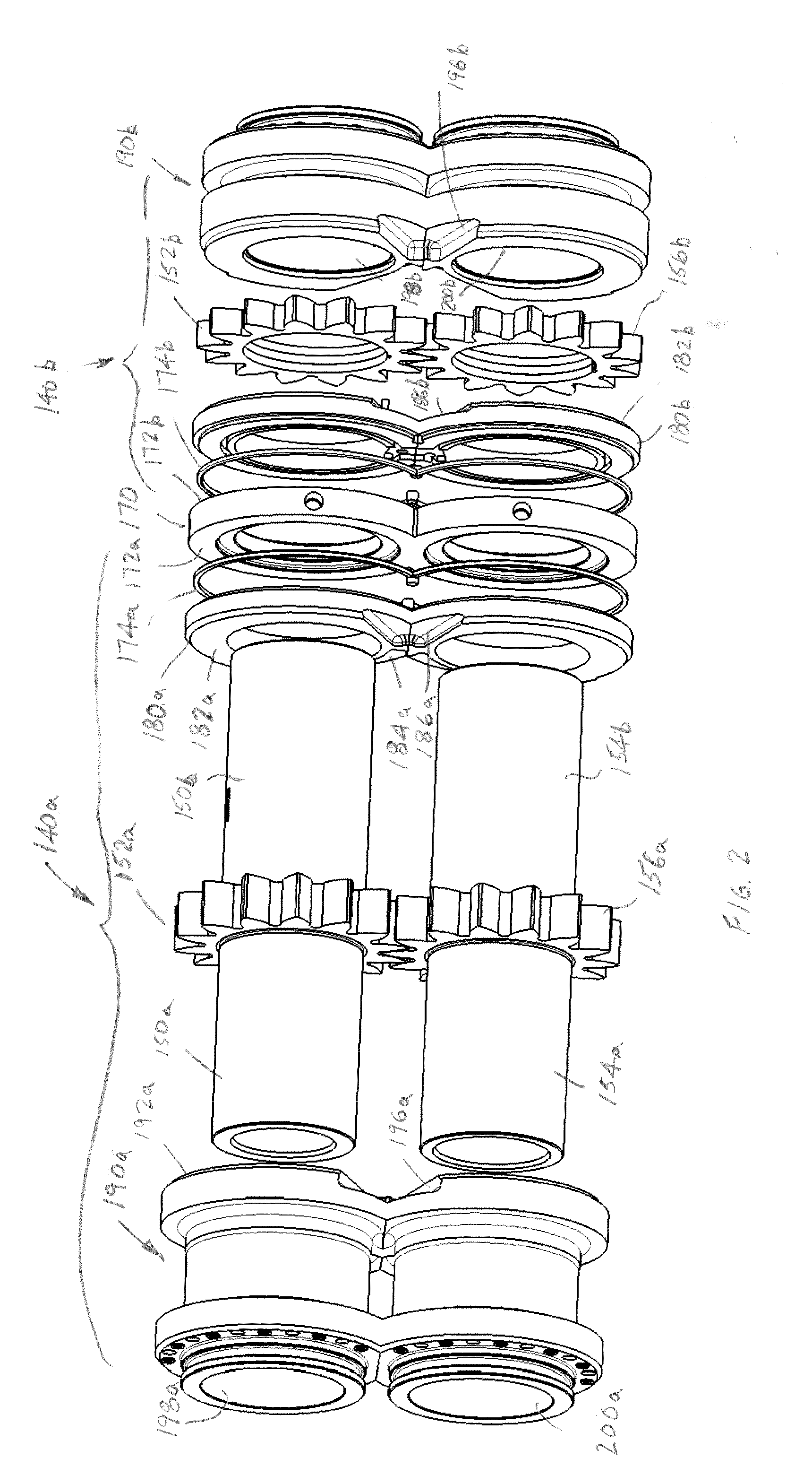
[0021]Portions of a fuel supply system 100 are shown in FIG. 1 and include a low pressure centrifugal pump 110 and a multistage positive displacement pump assembly or gear pump assembly 120. In FIG. 1, the multistage pump assembly 120 includes a housing 122 having a first end portion 124, and a second end portion 126 interconnected by a central sleeve 128. The sleeve 128 is secured at opposite ends to the first and second housing end portions 124, 126, respectively. For example, fasteners secure the end portions to the ends of the sleeve. In addition, the sleeve portion 128 of the housing includes a constant diameter bore or opening 130 extending therethrough. In this manner, the housing portion 124 forms a first shoulder at 132 and the second housing portion 126 forms a second shoulder 134 at the opposite end. Between these shoulders and along the extent of the throughbore 130 are received first and second gear pumps 140a, 140b. For purposes of brevity and ease of understanding, si...
PUM
| Property | Measurement | Unit |
|---|---|---|
| diameter | aaaaa | aaaaa |
| sizes | aaaaa | aaaaa |
| axial length | aaaaa | aaaaa |
Abstract
Description
Claims
Application Information