Integrated clamp insulators

a technology of clamping and insulators, which is applied in the direction of supporting insulators, suspension/strain insulators, electrical equipment, etc., can solve the problems of real clamp separation from the insulator, the possibility of less effective crimping, and the danger of safety hazards

Inactive Publication Date: 2013-02-07
PACIFIC POLYMERS
View PDF3 Cites 3 Cited by
  • Summary
  • Abstract
  • Description
  • Claims
  • Application Information

AI Technical Summary

Benefits of technology

[0007]As will be appreciated, the insulator body and clamp are formed from the same non-conducting material. Preferably the insulator body and clamp are of a cast-as-one construction. An epoxy resin based moulded product containing hydrophobically treated filler is preferred. Moulding offers an advantage in that the moulded product is uniform in composition throughout, leading to consistency in strength and electrical resistance. The latter has a benefit in reduction of the probability of electrical discharge across the insulator. Alternatively, a reinforced plastics material may be used.
[0009]Washers may be interposed between the head of the bolt and the clamp body and the nut and the body of the keeper to spread the load and reduce pressure on the bodies of the clamp and keeper as the clamp and keeper are brought together to clamp an electrical conductor.
[0013]The integrated insulator body and clamp system of the invention provides an advantage over prior devices as it reduces the number of connections between parts (namely, removing the need for a connection between the clamp and the insulator body), thereby reducing the probability of failure at a point of connection as a result of stresses in use.
[0014]The reduction in the number of components in the integrated insulator body and clamp produces labour savings in assembly of the insulator and clamping of a conductor on site. There is no need to attach clamp top heads that normally have to be crimped or bolted to insulator ends either at the manufacturing site or in the field.
[0016]When the clamp and keeper are formed from the same non-conducting material as the insulator (which is preferred), the possibility of metal to metal gaps is significantly reduced, if not eliminated. This lessens the prospect of electrical potential differences being created across such gaps by an energized electrical conductor resulting in discharges which produce radio and television signal interference. The use of non-conductive materials in the clamp and keeper results in improved electrical insulating performance due to an increased electrical arc distance and increased creepage distance and thus pollution resistance when compared to a comparable insulator body of the same length and configuration fitted with a metal end cable clamp.

Problems solved by technology

Mechanical clamps used in conjunction with insulators have been in use for 30 or 40 years and while they have proven to be an improvement over top tie insulators, they suffer from a number of problems, arising from their construction and multiplicity of components.
However, this poses a problem in that the clamp and the insulator are formed separately and require mating before crimping can occur.
Furthermore, in use and under load, the possibility of the crimping becoming less effective and the clamp separating from the insulator is real.
This can pose safety problems when live or potentially live conductors are to be clamped.

Method used


Image

  • Integrated clamp insulators
  • Integrated clamp insulators
  • Integrated clamp insulators

Examples


Embodiment Construction

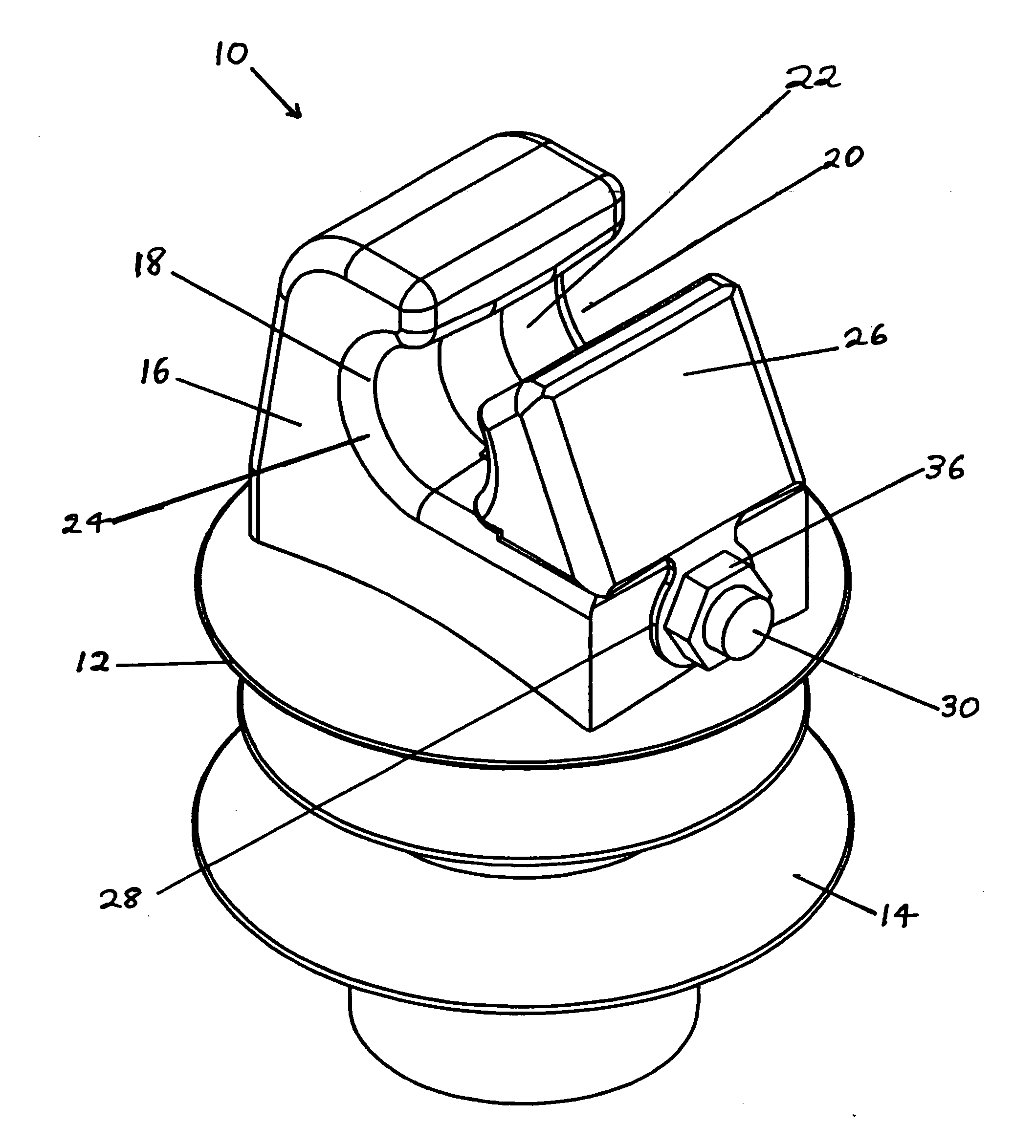
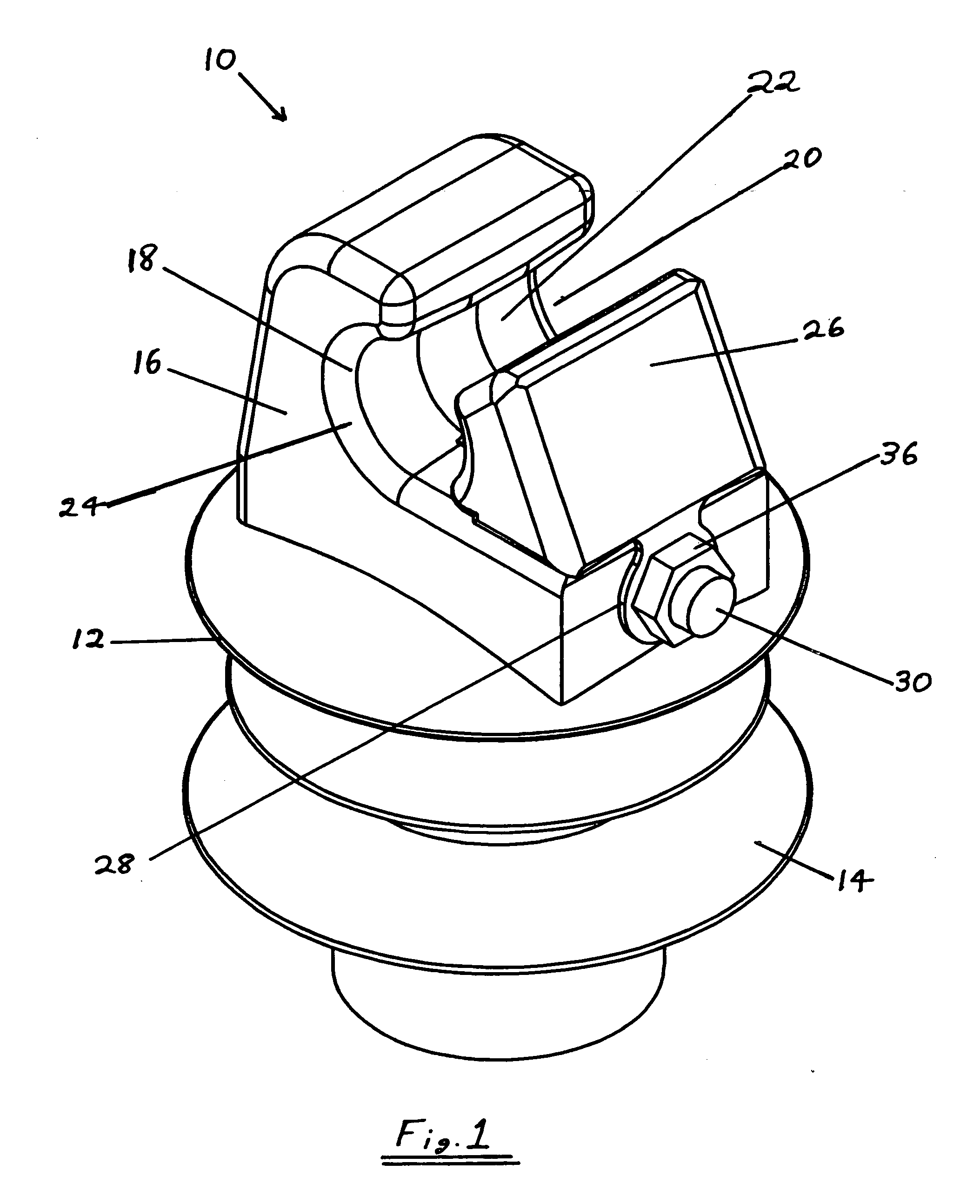
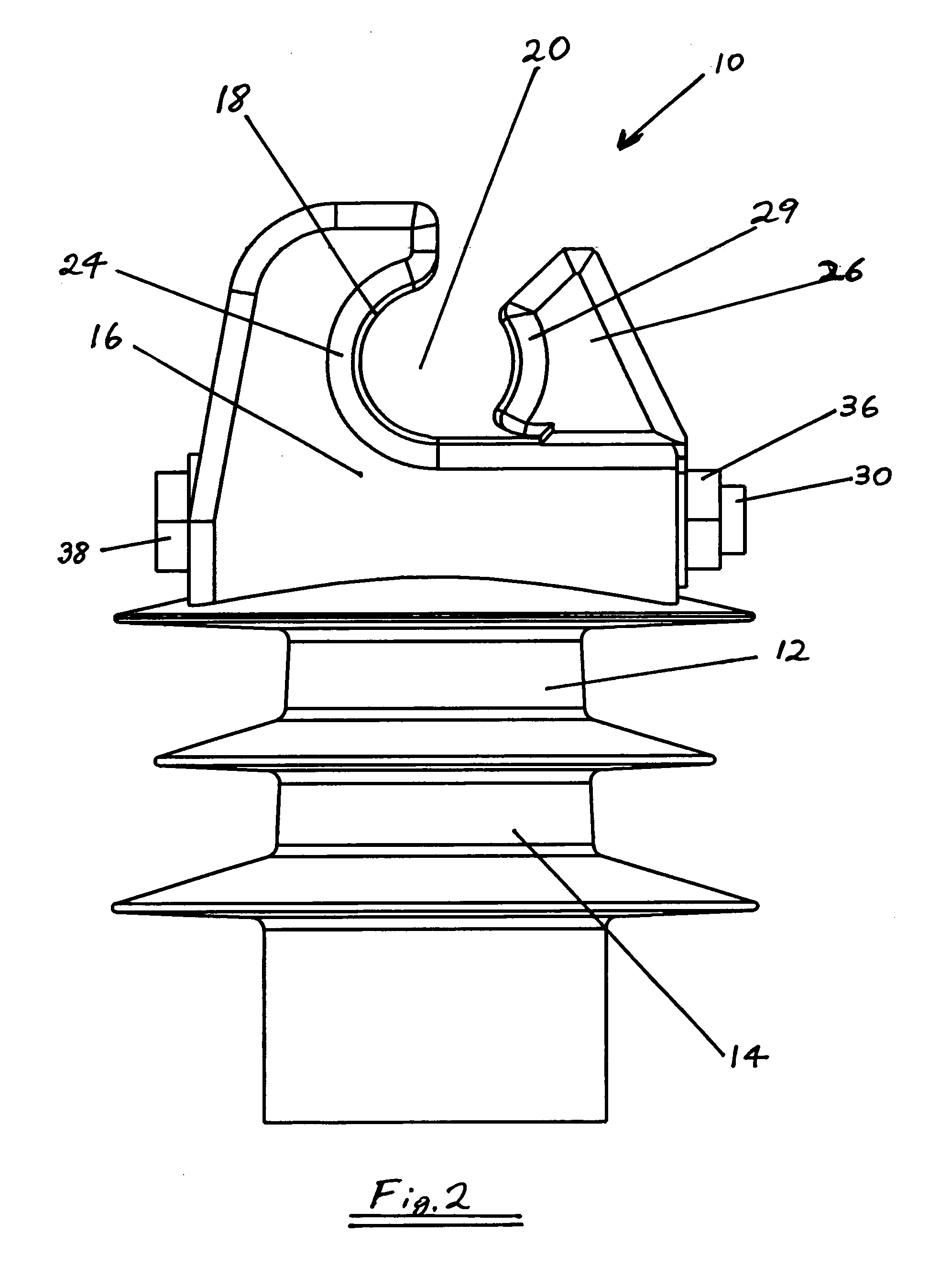
[0006]According to one aspect of the invention there is provided an electrical insulator incorporating a universal end clamp, said insulator comprising an insulator body and a clamp being formed as an integral piece, wherein the insulator body has a base fitting for attachment to a support structure at one end with the clamp being formed at the other end. The clamp has a body defining a saddle or recess for receiving an electrical conductor whether the insulator is extending either horizontally or substantially vertically from the support structure, and a bolt upon which a keeper or retainer is movable along a track defined in the body of the clamp for securing an electrical conductor in the saddle or recess.

[0007]As will be appreciated, the insulator body and clamp are formed from the same non-conducting material. Preferably the insulator body and clamp are of a cast-as-one construction. An epoxy resin based moulded product containing hydrophobically treated filler is preferred. Mo...


PUM

PropertyMeasurementUnit
electrical insulatoraaaaaaaaaa
electrically insulatingaaaaaaaaaa
electrically conductingaaaaaaaaaa

Abstract

An electrical insulator (12) comprising an insulator body (14) and a clamp (16) formed as an integral piece, wherein the insulator body has a base fitting for attachment to a support structure at one end with the clamp (16) being formed at the other end, said clamp having a body including a saddle (18) defining a hollow (20) for receiving an electrical conductor whether the electrical insulator is extending either substantially horizontally or substantially vertically from the support structure, and a bolt (30) upon which a keeper or retainer (26) is movable along a track (28) defined in the body of the clamp for securing an electrical conductor in the hollow (20).

Description

FIELD OF THE INVENTION[0001]This invention relates to clamps for receiving conductors, specifically clamps integrated into insulators for receiving and holding securely electrical conductors.BACKGROUND OF THE INVENTION[0002]The attachment of an electric power conductor, such as a cable, to support structures such as a pole or a pylon requires the use of an insulator and conductor secure means. Usually the conductor secure means is a form of clamp. Mechanical clamps used in conjunction with insulators have been in use for 30 or 40 years and while they have proven to be an improvement over top tie insulators, they suffer from a number of problems, arising from their construction and multiplicity of components.[0003]“One piece” electrical power line insulators have been described in U.S. Pat. No. 5,837,943. These have a universal end clamp suitable for substantially horizontal or vertical applications, with a preferred embodiment being a line post insulator having a universal end clamp...

Claims


Application Information

Patent Timeline
Patent Type & Authority Applications(United States)
IPC IPC(8): H01B17/16
CPCH02G7/053H01B17/16H01B17/06
Inventor BAKER, ALFCHESSUM, GORDONSORENSEN, ANDREW
Owner PACIFIC POLYMERS
Why Eureka
Try Eureka