
Container and closure assembly

a technology of container and closure, applied in the field of assembly, can solve the problems of inconvenient removal of the closure from the container, the closure may still be difficult to remove from the container,

Inactive Publication Date: 2010-10-28
TECH II
View PDF49 Cites 149 Cited by
  • Summary
  • Abstract
  • Description
  • Claims
  • Application Information

AI Technical Summary

Benefits of technology

[0009]According to one embodiment of the present disclosure, a container and closure assembly is provided. A container and closure assembly includes a container defining an opening and having a lip positioned around the opening. The lip defines a top surface, a bottom surface, and an outer surface therebetween. The container and closure assembly also includes a closure configured to be attached to the container. The closure includes a top portion defining a circular periphery, and a first skirt portion extending downwardly from the circular periphery to form a cylindrical structure defining a first internal closure space. The closure also includes a second skirt portion extending downwardly from a first part of the cylindrical structure. The second skirt portion has a first side edge and a second side edge that are spaced apart from each

Problems solved by technology

Removal of the closure from the container does not require a separate tool; however, removal of the closure from the container may be relatively difficult since the closure may need to be temporarily distorted and forced over the lip.
Such closures, nonetheless, may still be difficult to remove from a container because the locking portions may require use of a relatively large removal force or may be inconveniently situated.
Additionally, known locking portions that do not require the use of a large removal force tend to only lightly engage the container and may easily become undesirably separated from the container.

Method used


Image

  • Container and closure assembly
  • Container and closure assembly
  • Container and closure assembly

Examples


Embodiment Construction

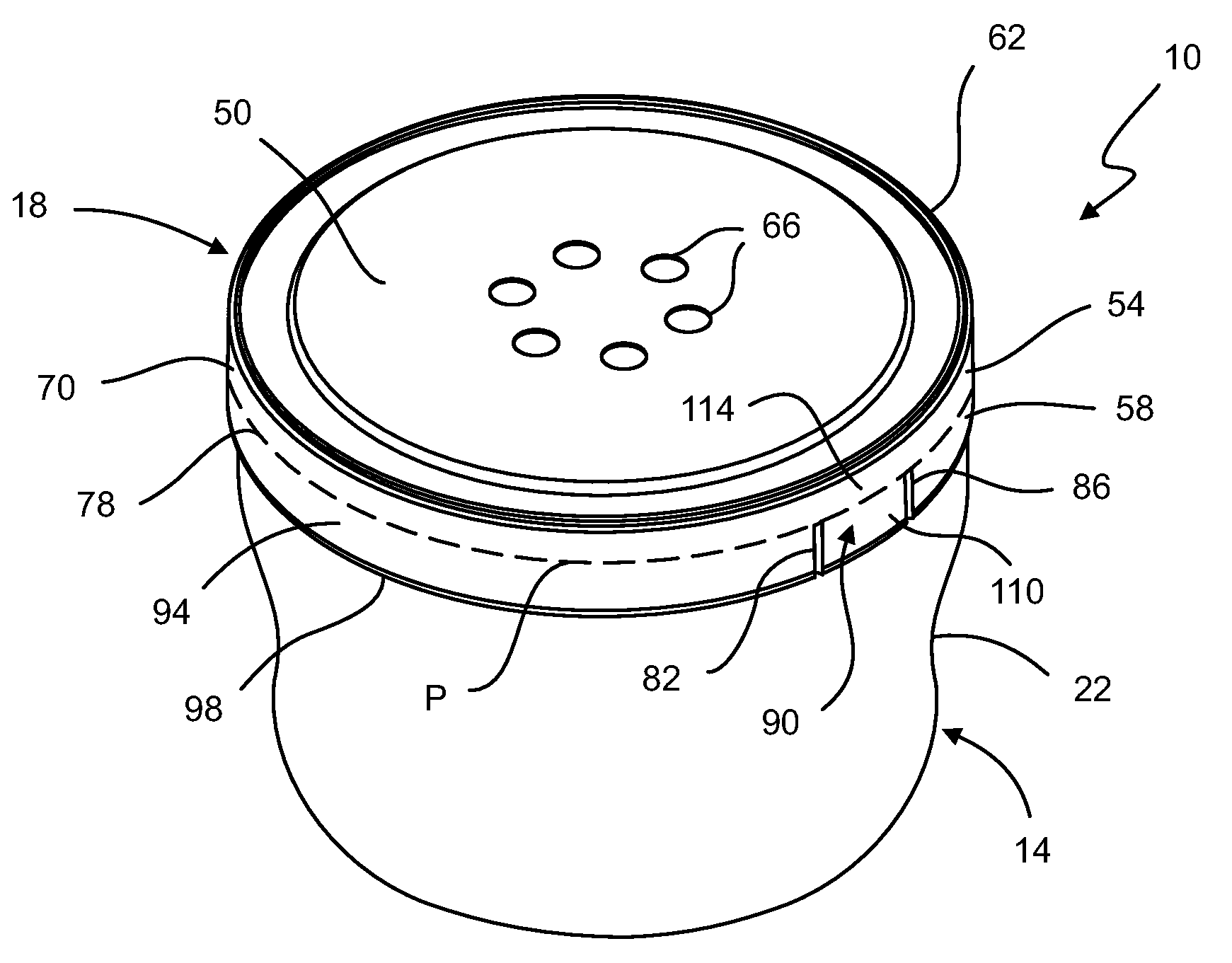
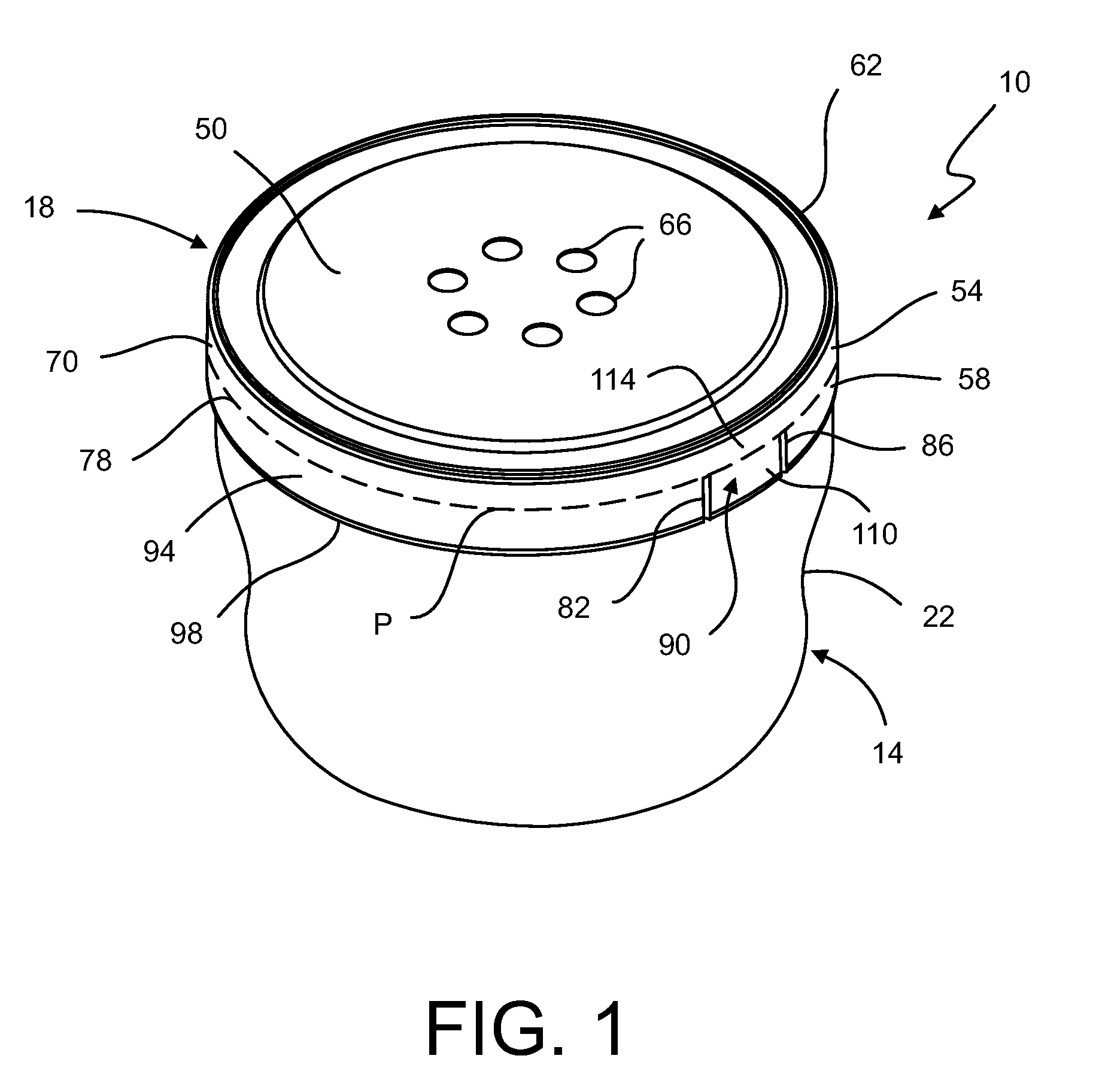
[0019]According to the present disclosure and referring now to FIG. 1, a container and closure assembly 10 is shown. The container and closure assembly 10 includes a container 14 and a closure 18. The container 14 holds a quantity of dry, liquid, and / or semi-liquid product. In particular, the container 14 may be used to contain a food product for human consumption. Accordingly, the container 14 may be made from materials that are conventionally used for the storage and after-purchase heating of food products. Specifically, the container 14 may be made from materials that enable a user to heat the food product stored within the container 14 by placing the container 14 in a microwave oven, as described below.

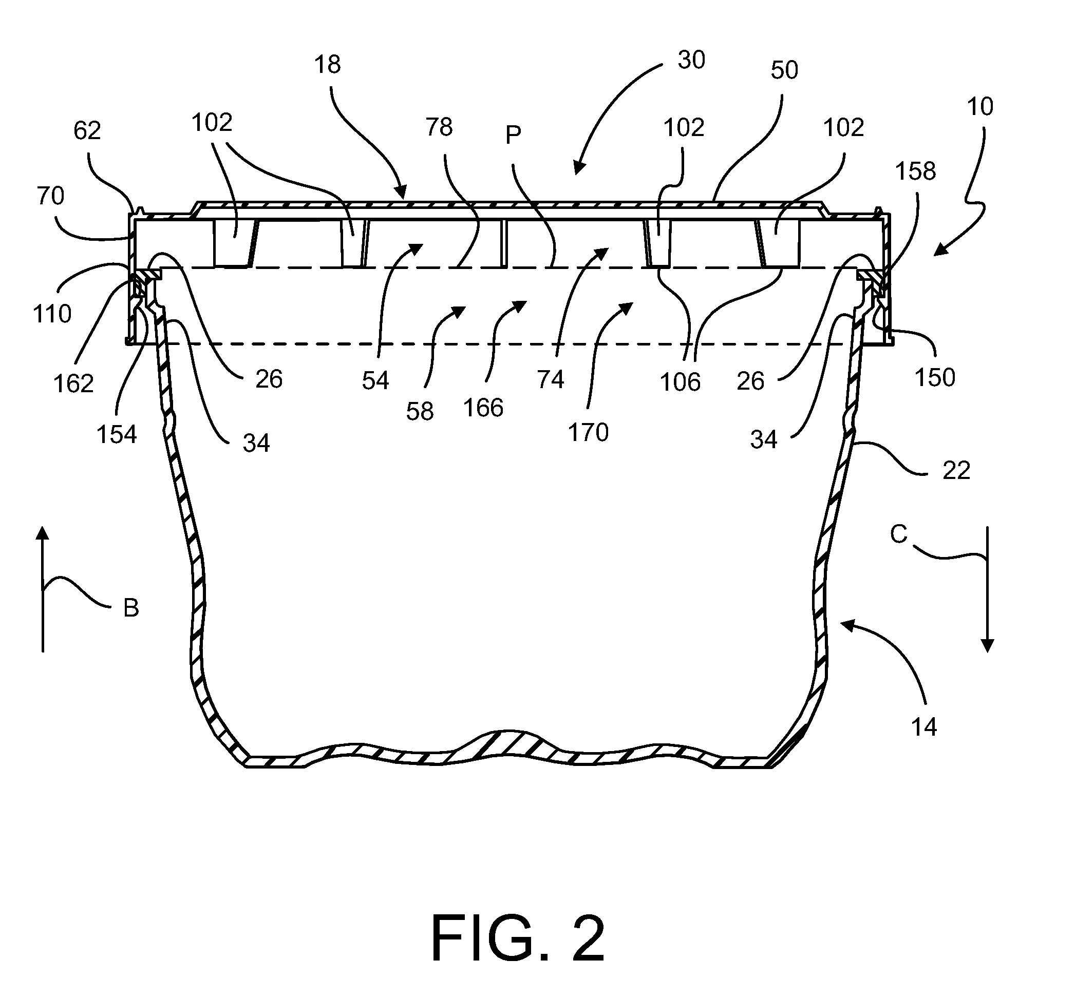
[0020]As shown in FIG. 2, the container 14 includes a body 22 and a lip 26. The body 22 may have any shape that is suitable to contain a food product. For instance, the body 22 may have an approximately cylindrical, elliptical, rectangular, or other polygonal shape. The bottom of ...


PUM


Abstract

A container and closure assembly includes a container defining an opening and having a lip positioned around the opening. The assembly also includes a closure configured to be attached to the container. The closure includes a top portion defining a circular periphery, and a first skirt portion extending downwardly from the circular periphery to form a cylindrical structure defining a first internal closure space. The closure also includes a second skirt portion extending downwardly from a first part of the cylindrical structure. The second skirt portion has a first side edge and a second side edge that form a gap. A tab extends downwardly from a second part of the cylindrical structure and is positioned in the gap. A first vertex segment is attached to the second skirt portion, and a second vertex segment is attached to the tab.

Description

FIELD OF THE INVENTION[0001]The present disclosure generally relates to assemblies that include a container and a removable closure associated therewith. More specifically, the present disclosure relates to a closure having a tab, which is configured to facilitate removal of the closure from an associated container.BACKGROUND OF RELATED ART[0002]Container assemblies are useful for storing products therein. In particular, container assemblies may be used to store prepared food products, such as soups, pastas, and other foodstuffs. Container assemblies may include a container and a removable a closure. The container includes a removable top portion that may be separated from the rest of the container to expose the contents therein. In use, the container holds a quantity of dry, liquid, or semi-liquid product, such as foodstuffs, therein. The container may have a generally cylindrical shape and a generally flat bottom. The cylindrical portion of the container defines a cavity suitable ...

Claims


Application Information

Patent Timeline
IPC IPC(8): B65D45/00
CPCB65D43/0256B65D81/3453B65D2205/02B65D2581/3428B65D2543/00296B65D2543/00564B65D2543/00092
Inventor SHIFFER, DAVID A.
Owner TECH II
Learn More