
Fault detection and shutdown control circuits and methods for electronic ballasts

a control circuit and fault detection technology, applied in the field of electronic ballasts, can solve problems such as the shutdown of the power conversion circuit, and achieve the effect of avoiding the shutdown of the ballas

Inactive Publication Date: 2010-10-28
PANASONIC INTELLECTUAL PROPERTY MANAGEMENT CO LTD
View PDF4 Cites 7 Cited by
  • Summary
  • Abstract
  • Description
  • Claims
  • Application Information

AI Technical Summary

Benefits of technology

[0010]The present invention has an object to provide an electronic ballast capable of avoiding a ballast shutdown caused by erroneously determining a fault condition.
[0014]According to the present invention, useless consumption of electric power by a fault condition that is not eliminated during the repeated starting operation can be avoided.
[0017]According to the second aspect of the invention, after the supply side fault detection circuit determines a fault condition, if the supply side fault detection circuit still determines the fault condition at the time of completion of the repeated starting operation, the control circuit stops at least the output of the power conversion circuit. Therefore, it is possible to avoid useless consumption of electric power by a fault condition that is not eliminated during the repeated starting operation.

Problems solved by technology

Therefore, a shutdown of the power conversion circuit caused by a fault condition that is erroneously determined in the load side fault detection circuit, in combination with a fault of the DC power supply circuit, is inhibited.

Method used


Image

  • Fault detection and shutdown control circuits and methods for electronic ballasts
  • Fault detection and shutdown control circuits and methods for electronic ballasts
  • Fault detection and shutdown control circuits and methods for electronic ballasts

Examples


Embodiment Construction

[0037]Hereafter, various embodiments of the present invention will be explained with reference to drawings.

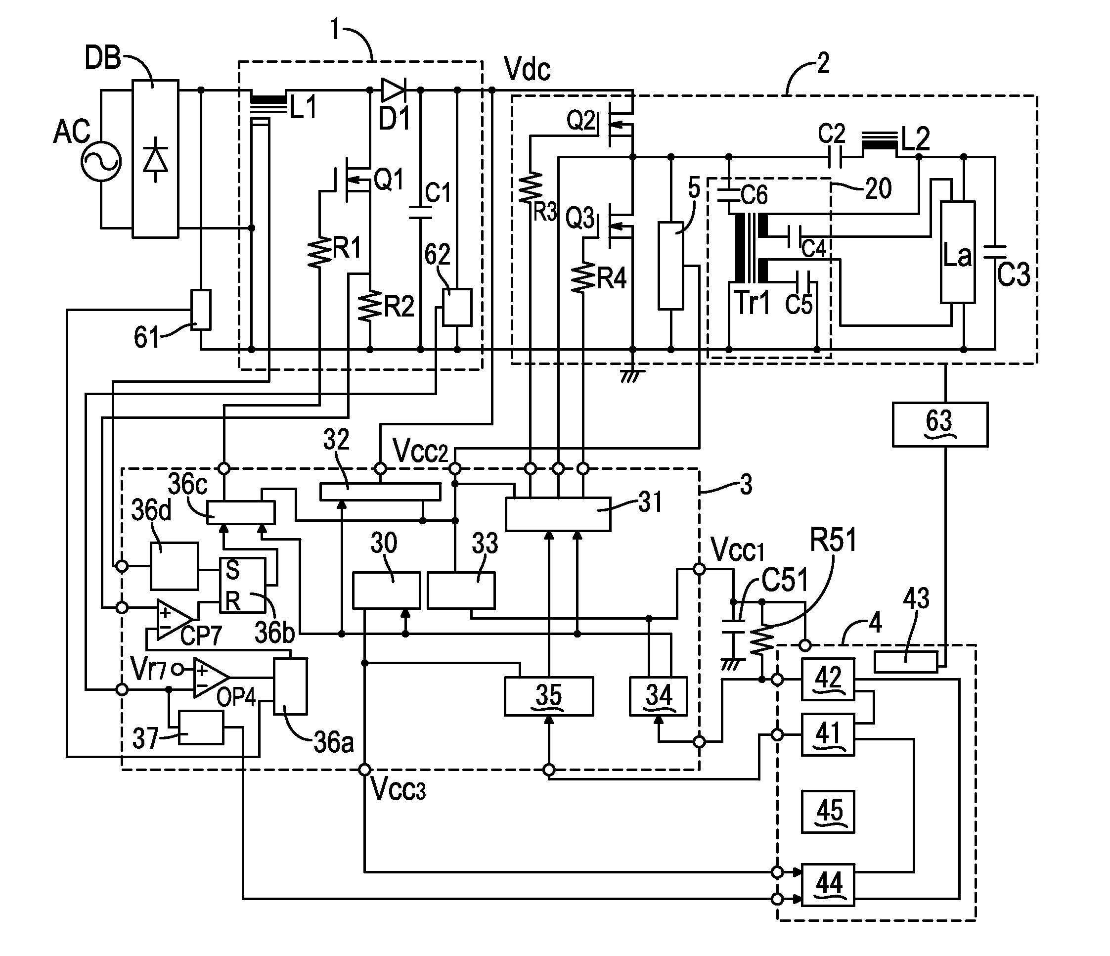
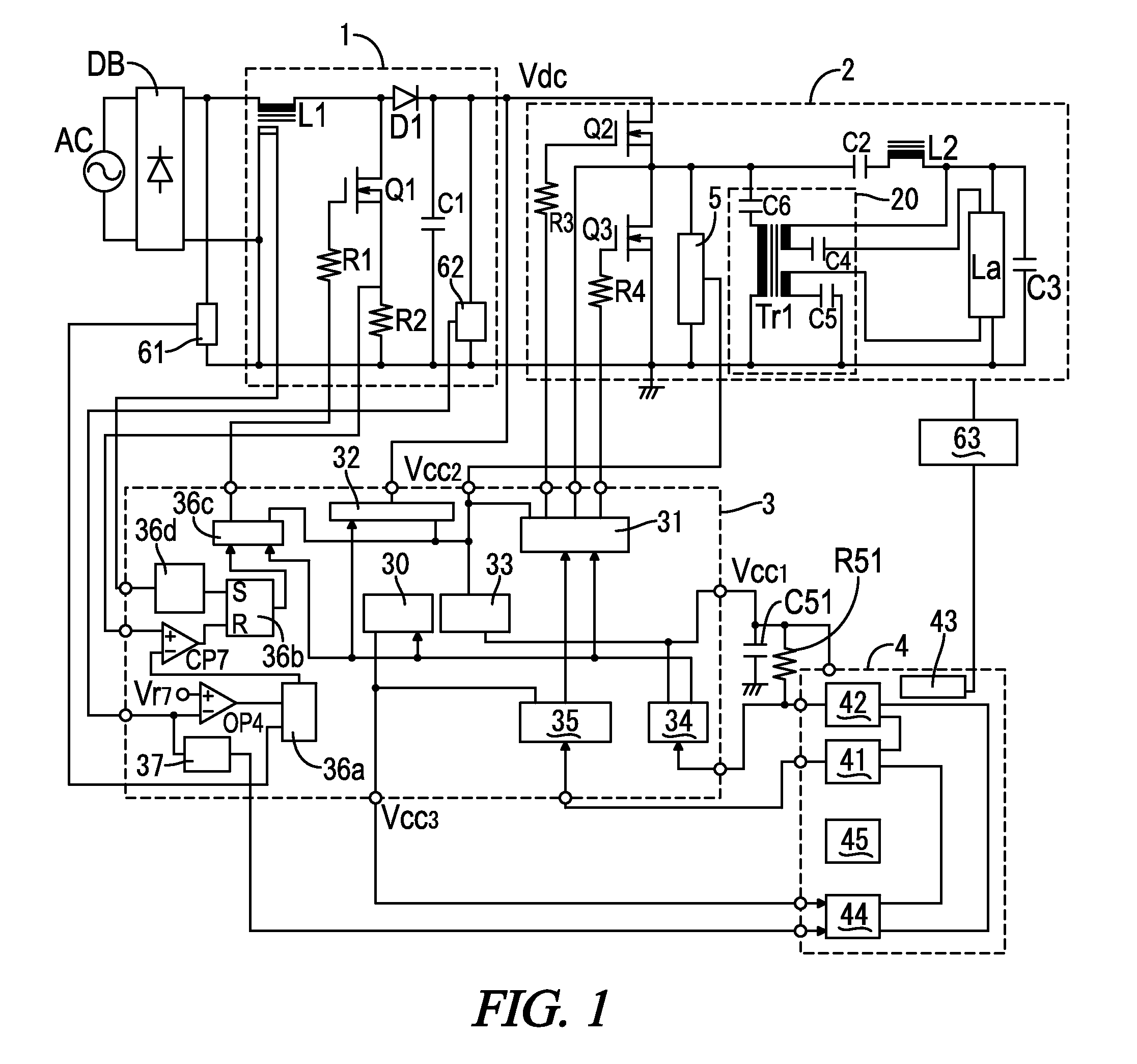
[0038]The present embodiment may be an electronic ballast used to provide operating power to a gas discharge lamp La having a pair of filaments (not illustrated) by supplying AC power thereto, as shown in FIG. 1. The ballast has a rectification circuit DB using a well-known diode bridge and performs full-wave rectification of AC power from an external AC power supply AC. A DC power supply circuit 1 receives the output of the rectification circuit DB and outputs DC power. A power conversion circuit 2 that converts the DC power from the DC power supply circuit 1 into AC power and supplies it to the discharge lamp La.

[0039]The DC power supply circuit 1 is a well-known booster chopper circuit (boost converter). More specifically, the DC power supply circuit 1 includes series circuit of an inductor L1 connected between the DC outputs of the rectification circuit DB (namely, between ...


PUM


Abstract

An electronic ballast is capable of inhibiting ballast shutdown caused by erroneously determining a fault condition. The ballast includes a DC power supply circuit for outputting DC power, a power conversion circuit that appropriately converts DC power outputted by the DC power supply circuit and outputs it to a discharge lamp, a DC voltage droop detection circuit for determining existence / absence of a fault condition in the DC power supply circuit 1, a lamp end of life detection circuit for determining existence / absence of a fault condition of the discharge lamp; and a sequence control circuit and a shutdown control circuit that control at least the power conversion circuit according to detection by the DC voltage droop detection circuit the discharge lamp life detection circuit. When a fault is determined in both the DC voltage droop detection circuit and the discharge lamp life detection circuit, an operation according to the detection of the DC voltage droop detection circuit, the sequence control circuit lowers the output of the power conversion circuit 2 is performed in priority to an operation that, according to the detection of the discharge lamp life detection circuit, the shutdown control circuit shuts down the power conversion circuit

Description

[0001]A portion of the disclosure of this patent document contains material that is subject to copyright protection. The copyright owner has no objection to the reproduction of the patent document or the patent disclosure, as it appears in the U.S. Patent and Trademark Office patent file or records, but otherwise reserves all copyright rights whatsoever.CROSS-REFERENCES TO RELATED APPLICATIONS[0002]This application claims benefit of the following patent application which is hereby incorporated by reference: Japan Patent Application No. 2009-107072, filed Apr. 24, 2009.STATEMENT REGARDING FEDERALLY SPONSORED RESEARCH OR DEVELOPMENT[0003]Not ApplicableREFERENCE TO SEQUENCE LISTING OR COMPUTER PROGRAM LISTING APPENDIX[0004]Not ApplicableBACKGROUND OF THE INVENTION[0005]The present invention relates to electronic ballasts for providing operating power to gas discharge lamps. More particularly, the present invention pertains to fault detection and shutdown control circuits and methods fo...

Claims


Application Information

Patent Timeline
Patent Type & Authority Applications(United States)
IPC IPC(8): H05B41/36
CPCH05B41/2981H05B41/295
Inventor ONISHI, NAOKIASANO, HIROYUKIHAMANA, TETSUYAYAMANAKA, MASAHIRO
Owner PANASONIC INTELLECTUAL PROPERTY MANAGEMENT CO LTD
Learn More