Digital camera with overscan sensor

a digital camera and sensor technology, applied in the field of motion picture cameras, can solve the problems of inability to meet the demands occurring in disadvantageous for the imaging performance of optical systems, and inability to meet the requirements of all typical recording situations in terms of handling and picture quality, etc., to achieve the effect of simplifying the interruption-free change of memory devices, reducing the weight of the camera, and increasing data security

Inactive Publication Date: 2010-10-28
ARNOLD & RICHTER CINE TECH GMBH & CO BETRIEBS KG
View PDF20 Cites 3 Cited by
  • Summary
  • Abstract
  • Description
  • Claims
  • Application Information

AI Technical Summary

Benefits of technology

[0006]In the motion picture camera in accordance with the invention, a sensor device is therefore provided having a plurality of photoelectrical sensor elements which each produce an electrical received signal. These received signals are digitized while still in the camera, optionally after amplification, so that the picture information is present directly in a digital format and can thus be electronically processed without problem and can be reproduced without substantial loss of quality.
[0064]Finally, it is preferred for the motion picture camera to have a modular design in order to allow a simple and fast replacement of electronic, optical and mechanical modules and in order furthermore to allow the use of conventional camera components. In particular, the sensor device together with the control device, further a recording optical system, or a memory device can respectively form its own such modular unit.

Problems solved by technology

However, the development and the printing of such a negative film are undesirably complex and / or expensive since specialist equipment is required.
However, such video cameras do not satisfy the demands occurring in all typical recording situations with respect to handling and picture quality and they are consequently not used in full motion recordings in which a particularly high picture quality is desired.
For example, such a camera design with three CCD sensors requires recording lenses with a comparatively long back focal length, which is disadvantageous for the imaging performance of the optical systems.
Furthermore, splitter prisms are required in the optical reception path which can likewise result in an unwanted reduction in the recording quality.

Method used


Image

  • Digital camera with overscan sensor
  • Digital camera with overscan sensor
  • Digital camera with overscan sensor

Examples


Embodiment Construction

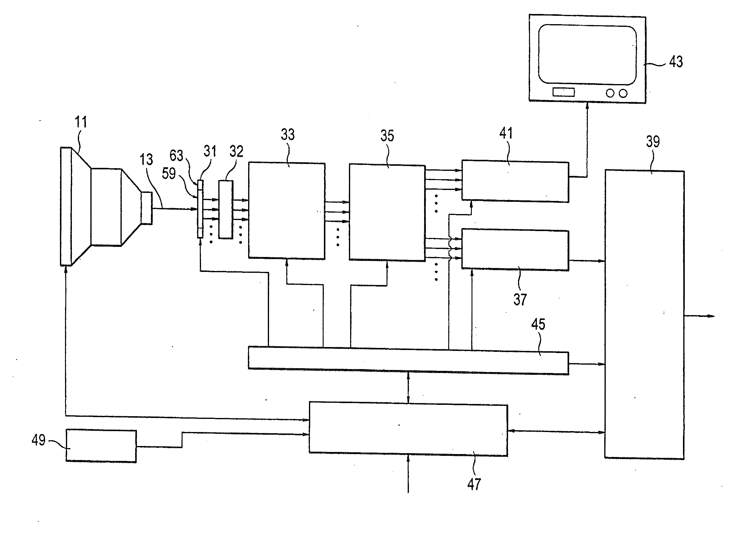
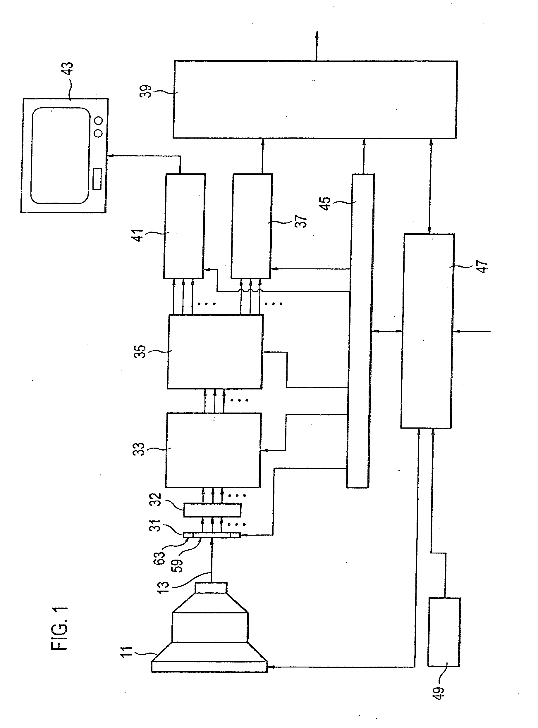
[0069]FIG. 1 shows a possible design of the motion picture camera in accordance with the invention. This has a recording optical system 11 which images the motion picture actually to be recorded along a reception beam path 13 on an optoelectronic sensor device 31. In a matrix-like arrangement, the sensor device 31 has a plurality of sensor elements which can, as a consequence of the light exposure, produce a respective received signal which corresponds to the light intensity and the exposure time. For example, the sensor device 31 can have an arrangement of 1920×1080 or 2880×2160 of such sensor elements.

[0070]The received signals produced by the sensor device 31 are delivered in parallel, or partly in parallel, to an amplification device 32 which has a corresponding number of electronic amplifiers. The received signals amplified in this manner are digitized in a downstream digitizing device 33 by a corresponding number of analog / digital converters. The digitizing device 33 is connec...


PUM


Abstract

An electronic motion picture camera for recording a sequence of images includes a sensor device having a two-dimensional arrangement of sensor elements that generate electrical signals in dependence on an exposure to light. A first group of the sensor elements forms a recording region of the sensor device and generates recording signals, and a second group of the sensor elements forms a monitoring region of the sensor device and generates monitoring signals, wherein the monitoring region surrounds the recording region. A memory device stores the recording signals, but not the monitoring signals. A display device displays the recording signals, the monitoring signals and a frame signal representing a border between the recording region and the monitoring region of the sensor device, and the border between the recording region and the monitoring region is kept fixed during the recording of the sequence of images.

Description

RELATED APPLICATIONS[0001]This application is a continuation of U.S. patent application Ser. No. 10 / 355,939, filed Jan. 31, 2003, entitled Digital Camera With Over-scan Sensor, the contents of which are incorporated herein by reference in their entirety.BACKGROUND OF THE INVENTION[0002]The invention relates to a motion picture camera for full motion recordings of high picture quality such as television movies, cinema commercials, cinema movies or even industrial or medical applications. Motion picture cameras for the exposure of a photochemical negative film are known for such recordings. This recording technology allows a high resolution, large brightness dynamics and good color rendering. However, the development and the printing of such a negative film are undesirably complex and / or expensive since specialist equipment is required. Furthermore, it is required for an electronic picture processing, which has become customary in the meantime—for example for the changing of the color...

Claims


Application Information

Patent Timeline
Patent Type & Authority Applications(United States)
IPC IPC(8): H04N5/235H04N5/232
CPCH04N5/23293H04N23/63
Inventor KANDLEINSBERGER, ROBERTKHANH, TRAN QUOCKOPPETZ, MICHAELPOPP, HERMANN
Owner ARNOLD & RICHTER CINE TECH GMBH & CO BETRIEBS KG
Why Eureka
Try Eureka