Rotation module for an inspection system

a technology of rotation module and inspection system, which is applied in the direction of television system, optical apparatus testing, instruments, etc., can solve the problems of inconvenient replacement of rotation module, inconvenient operation, and inconvenient use, and achieve the effect of simple and fast replacement of rotation modul

Active Publication Date: 2019-01-22
IPEK INT
View PDF10 Cites 0 Cited by
  • Summary
  • Abstract
  • Description
  • Claims
  • Application Information

AI Technical Summary

Benefits of technology

[0009]The slip ring enables the rotation module to be rotated in both directions by 360° and more independently of the rotation angle of the pivoting housing. By adjusting the rotation angle of the rotation module, an image taken by a camera arranged on the rotation module may be taken in the correct position, and does not have be edited in order to obtain an image in the correct position. Further, a tool provided on the rotation module may be rotated independently of the rotation axis of the pivoting housing.
[0011]In an embodiment of the invention, a first contact board is provided on the pivoting fork, and a second contact board is provided on the rotation module, wherein the first contact board may be coupled to the second contact board, and wherein the second contact board is operatively coupled to the slip ring. Thereby, the rotation module may be released from the pivoting housing and from the pivoting fork, respectively, especially easily such that, for example, a particular simple and fast replacement of a rotation module by another rotation module is enabled.
[0017]In the housing, preferably, two illumination means, preferably two light emitting diodes may be arranged. The light emitting diodes may be provided in order to illuminate the surroundings or, for example, to project measurement and reference points, respectively, onto an object to be measured and to be taken, respectively, by the imaging means. Because the illumination means are arranged within the housing, and the housing is held in the correct position, it is also ensured that also the spots to be created by the illumination means are also in the correct position. In particular, if the light spots created by the illumination means are also mapped to the images taken by the imaging means, it is ensured that in the images taken, also the light spots are in the correct position, which substantially simplifies the evaluation of the images taken.

Problems solved by technology

This, however, has the disadvantage that when using a rectangular image sensor, after a rotation of the image, there no longer is the entire image information present in the rotated image.
Further, the rotation of images is CPU-intensive which, in particular, for video images, is disadvantageous, if these have to be rotated almost in real time.

Method used


Image

  • Rotation module for an inspection system
  • Rotation module for an inspection system
  • Rotation module for an inspection system

Examples


Embodiment Construction

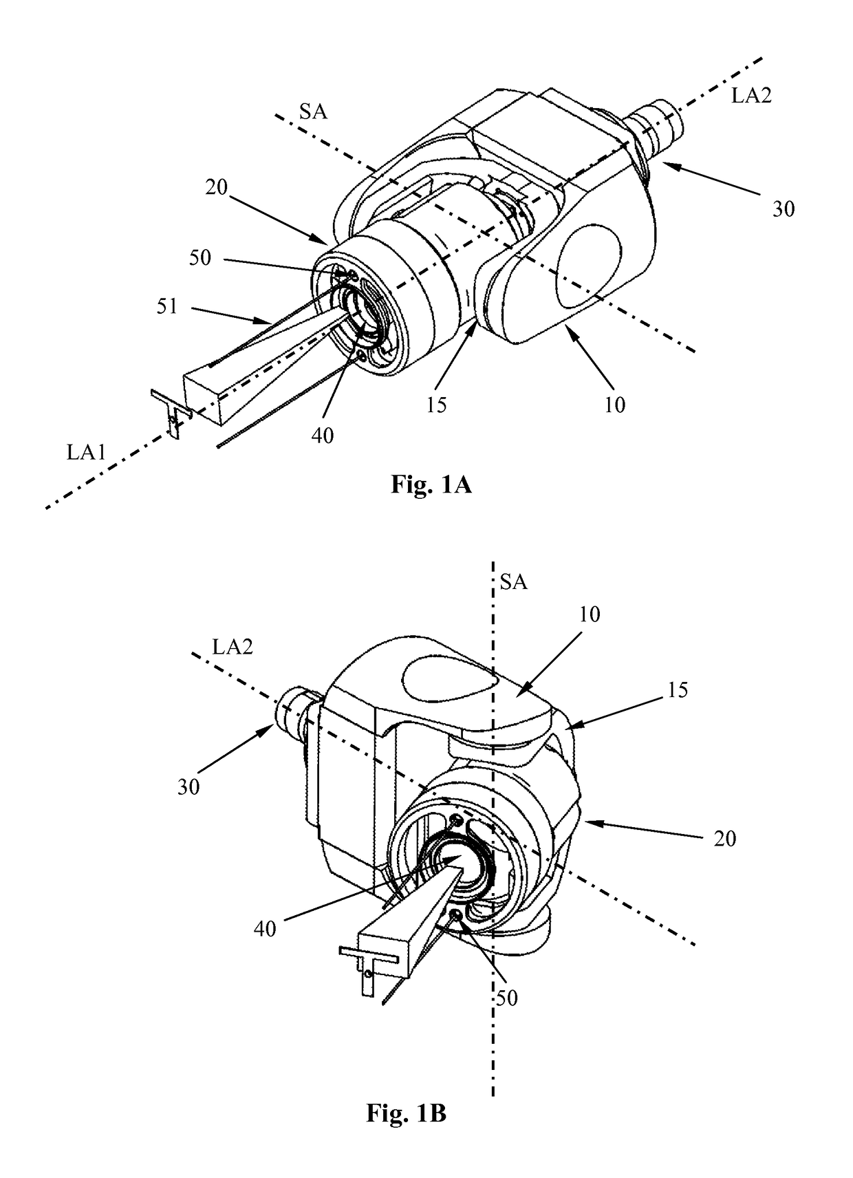
[0027]FIGS. 1A and 1B show a device according to the invention for an inspection system having a rotation module 20, which is coupled via a pivoting fork 15 to a pivoting housing 10.

[0028]In FIG. 1A, the device is shown it its normal position, whereas in FIG. 1B, the pivoting housing is rotated around its longitudinal axis LA2 by 90°, and the pivoting fork 15 is pivoted by approximately 45° about the pivot axis SA.

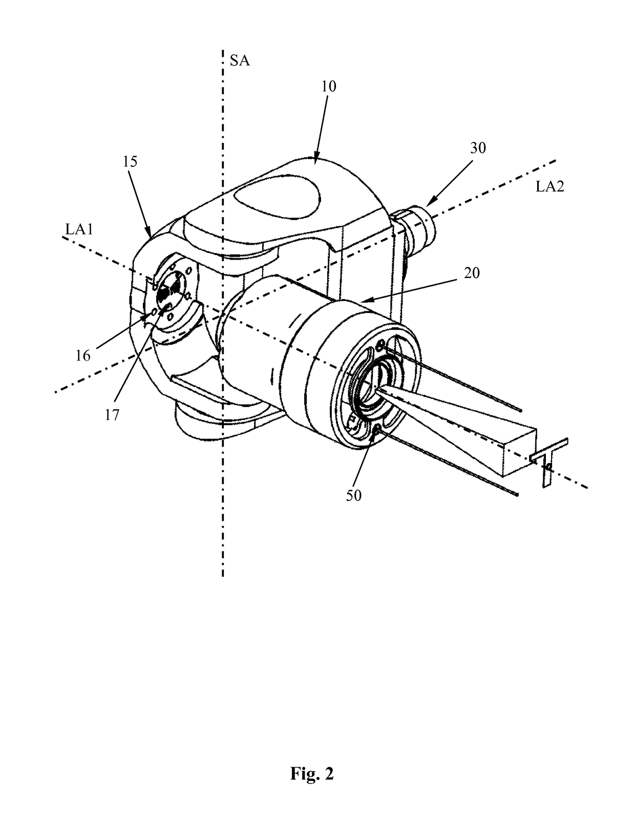
[0029]The device comprises a pivoting housing 10, which has at its rear end a rotation axis 30, via which the device, for example, may be connected to an inspection carriage or to a lifting means of the inspection carriage or to another device or connection device, or means of the inspection carriage. The pivoting housing is rotatable around its longitudinal axis LA2 in both directions by 360°, wherein the signal and energy transmission is carried out via a slip ring such that the pivoting housing may be rotated about the longitudinal axis LA2 virtually infinitely.

[0030]Be...


PUM


Abstract

The invention relates to a device for an inspection system, in particular, to a sewer and pipe, respectively, inspection system comprising a rotation module, which is coupled to a pivoting housing, wherein the rotation module is rotatable about its longitudinal axis relatively to the pivoting housing, and wherein the rotation module comprises a slip ring for signal and energy transmission, respectively, between the rotation module and the pivoting housing.

Description

CROSS REFERENCE TO RELATED APPLICATIONS[0001]This application claims priority to German Application No. 20 2013 104 188.2, filed Sep. 13, 2013, the contents of which are incorporated by reference herein.FIELD OF THE INVENTION[0002]The invention relates to a device for an inspection system, in particular, a sewer and pipe, respectively, cleaning system with a rotation module, as well as an inspection system having a device according to the invention.BACKGROUND OF THE INVENTION AND PRIOR ART[0003]For performing pipe and sewer inspections, respectively, it is known to use so-called sewer and pipe, respectively, inspection systems, which may be introduced into the sewer and drainage pipe, respectively, and may be moved, for example, may be displaced within the sewage pipe. The sewage pipe inspection systems may comprise an image acquisition means, for example, a camera and a video camera, respectively, which, for example, may be arranged on a carriage of the sewage pipe inspection syste...

Claims


Application Information

Patent Timeline
Patent Type & Authority Patents(United States)
IPC IPC(8): H04N5/253H04N7/18H04N5/225E03F7/00E03F3/00E03F7/12B08B9/04G01M3/00
CPCH04N7/183B08B9/04E03F3/00E03F7/00G01M3/005H04N5/2252H04N5/2256E03F7/12H04N2005/2255G01M11/081G03B37/005H04N23/555H04N23/56H04N23/51
Inventor HENN, PETERZAHND, FABIAN
Owner IPEK INT
Why Eureka
Try Eureka