Image display device having imaging device

a technology of image display device and manufacturing cost, which is applied in the field of image display device having an imaging device, can solve the problems of increasing so as to achieve the effect of reducing the quality of the image displayed by the image display device and rising the manufacturing cost of the image display devi

Inactive Publication Date: 2013-10-24
JOLED INC
View PDF17 Cites 4 Cited by
  • Summary
  • Abstract
  • Description
  • Claims
  • Application Information

AI Technical Summary

Benefits of technology

[0009]In an image display device to which a function of a pointing device is added, it is necessary to provide a pressure sensitive sensor. Thus, there is a problem that the manufacturing cost of the image display device rises, and there is also a problem that since an image is seen through the pressure sensitive sensor, the quality of the image displayed by the image display device is reduced.
[0012]Accordingly, it is desirable to provide an image display device having an imaging device in which in addition to a function of a pointing device, a function to acquire information relating to a position and the like of an observer can be added, and which can be manufactured at low cost and can condense a sufficient amount of light to the imaging device.
[0017]The image display device having the imaging device of the embodiment of the invention includes the position detecting means for obtaining the position information of the subject based on the image information acquired through the imaging device. Here, when the position detecting means continuously obtains the position information of the subject (for example, hand, finger, eyeball, etc.) in time series, the movement of the subject (for example, hand, finger, eyeball, line of sight) can be obtained, and various processes corresponding to the position and the movement of the subject (for example, hand, finger, eyeball, line of sight) can be performed. Alternatively, when the position detecting means obtains the direction in which the subject is directed, various processes corresponding to the direction in which the subject is directed can be performed. Besides, since a corresponding indication point on the image display part can be specified from the direction of the hand, pen or the like, the so-called pointer function can be added to the image display device having the imaging device. Further, since the imaging device is arranged on the back side of the image display part, as compared with a case where the imaging device is arranged at a place other than the back of the screen, the image of the subject can be taken more accurately, and the image of the face, eye, motion or the like of the user facing the image display part can be accurately taken by the imaging device. By this, the position information of the subject can also be accurately obtained, and the high-performance detection function for position information can be provided. Besides, in a three-dimensional image, based on the position information, an optimum three-dimensional image observation position can be indicated to the observer, or the observer can be guided to the optimum three-dimensional image observation position, or the optimum three-dimensional image can be provided according to the position of the observer.

Problems solved by technology

Thus, there is a problem that the manufacturing cost of the image display device rises, and there is also a problem that since an image is seen through the pressure sensitive sensor, the quality of the image displayed by the image display device is reduced.
Thus, the manufacturing cost of the image display device increases.
In the technique disclosed in JP-A-2005-010407, for example, as shown in FIG. 15 and FIG. 16 thereof, since the imaging device takes an image based on light passing through one light transmission part provided for plural pixels, it is difficult to condense a sufficient amount of light to the imaging device.

Method used


Image

  • Image display device having imaging device
  • Image display device having imaging device
  • Image display device having imaging device

Examples


embodiment 1

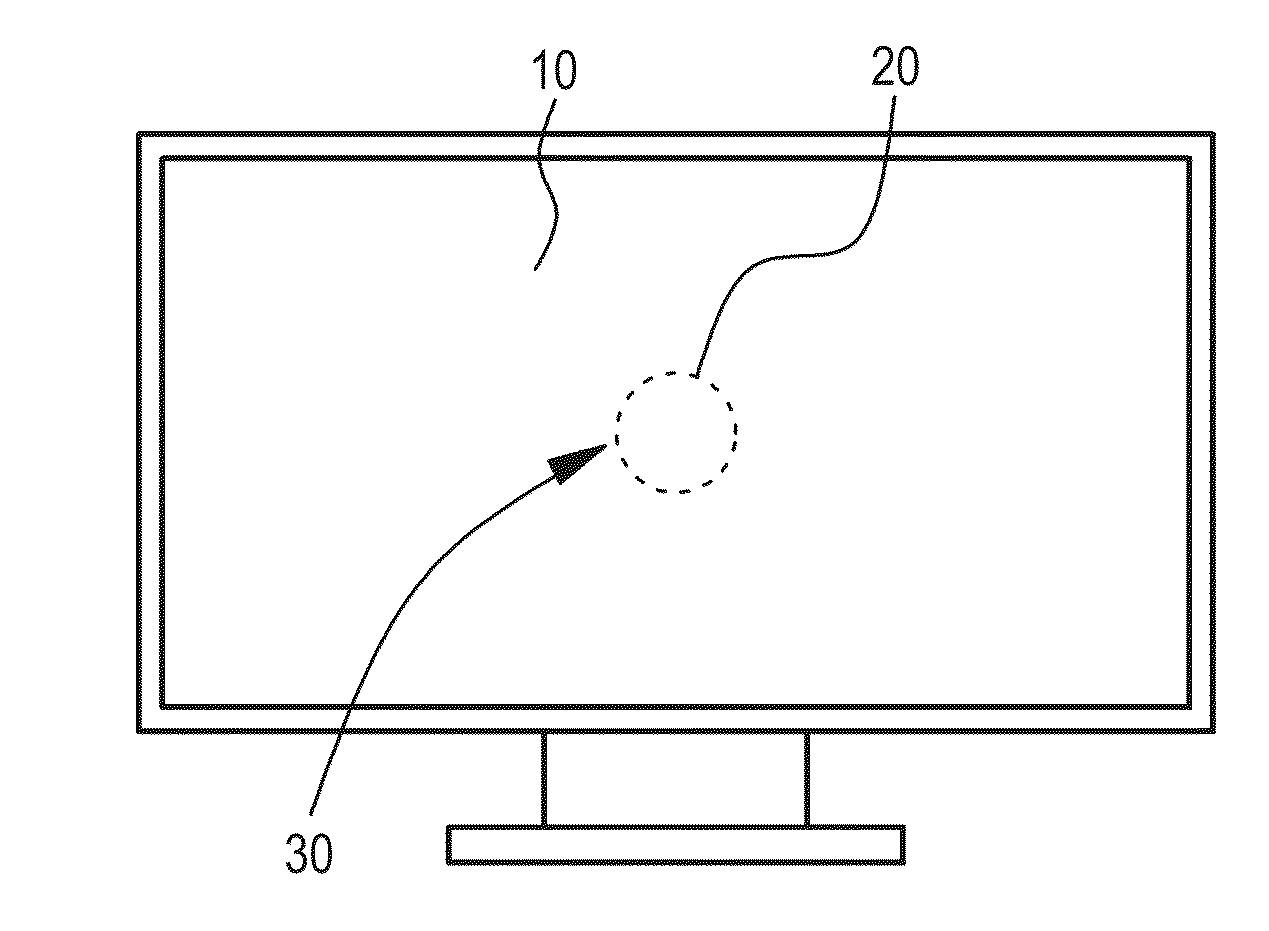
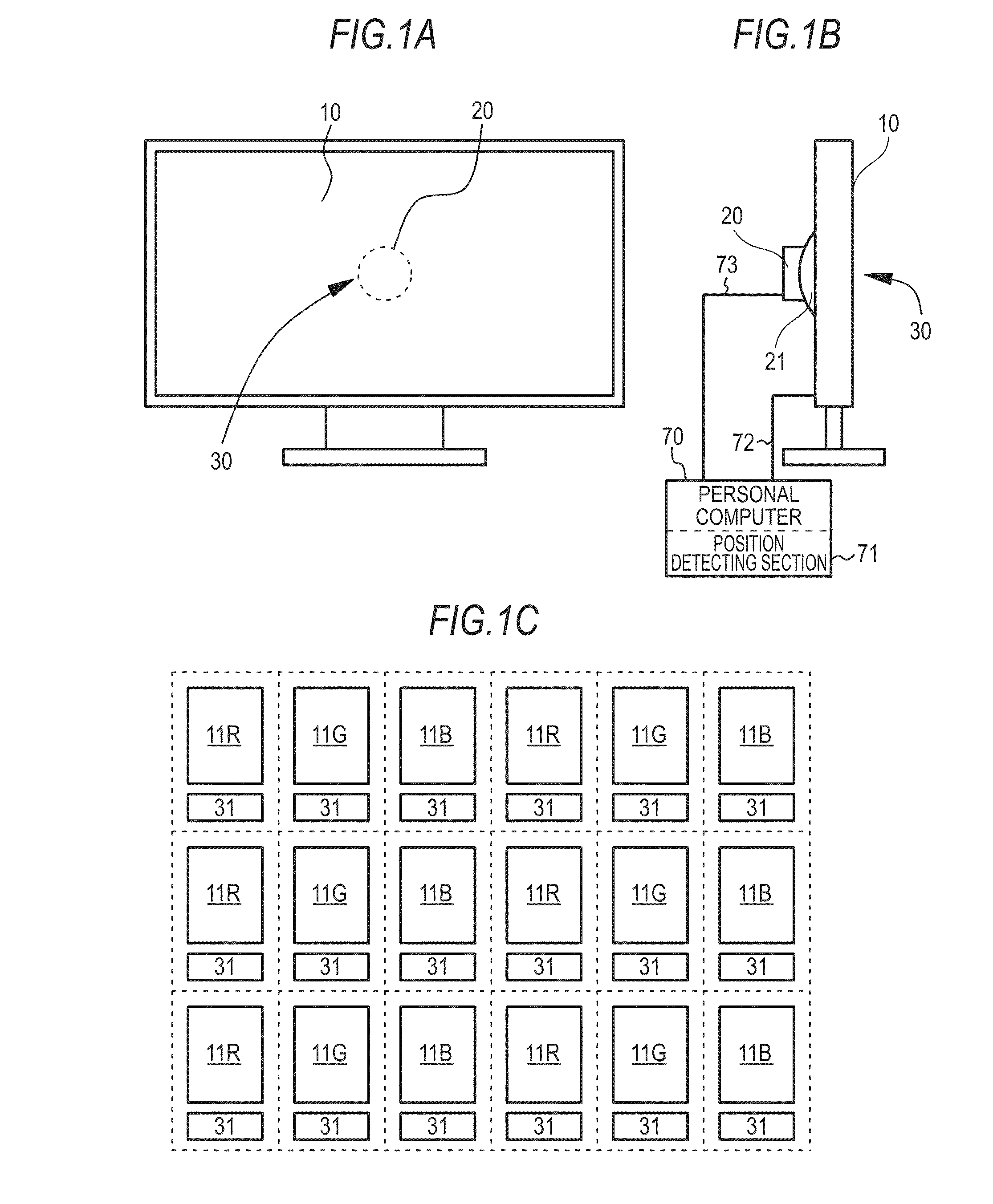
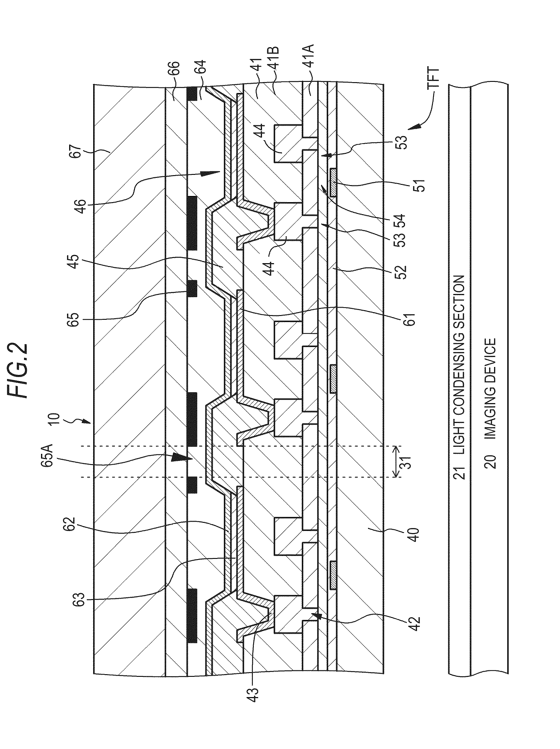
[0055]An embodiment 1 relates to the image display device having the imaging device according to the invention, specifically, the image display device having the imaging device according to the first mode of the invention. FIG. 1A and FIG. 1B are conceptual views showing the image display device having the imaging device of the embodiment 1 when viewed from front and from side, and FIG. 1C schematically shows the arrangement of plural pixels constituting an image display part. FIG. 2 is a schematic partial sectional view of the image display device having the imaging device.

[0056]The image display device having the imaging device of the embodiment 1 includes (A) an image display part 10 in which plural pixels 11 (11R, 11G, 11B) including light-emitting devices are arranged, (B) a light transmission region 30 provided in the image display part 10, (C) an imaging device 20 arranged on the back side of the image display part 10, (D) a light condensing section 21 configured to condense ...

embodiment 2

[0077]An embodiment 2 is a modification of the embodiment 1, and relates to the first configuration of the invention. In the embodiment 2, a photographed image is processed in order to obtain a higher quality photographed image.

[0078]In general, when light passes through a minute light transmission part 31, a so-called diffraction phenomenon occurs in the light transmission part 31. FIG. 6 is a schematic view for explaining the diffraction phenomenon caused by a slit. Here, the light transmission part 31 functions as the slit, and the same image as an image “C” appears as an image “A” and an image “B” at equal pitches by the diffraction phenomenon, and consequently, the image is blurred. FIG. 7A shows an image obtained by photographing after a transparent glass plate is arranged in front of the imaging device 20, and FIG. 7B shows an image obtained by photographing after a transparent glass plate provided with a light transmission part having a certain shape, size and distribution i...

embodiment 3

[0093]An embodiment 3 is a modification of the embodiment 2, and relates to the second configuration of the invention. As described in the embodiment 2, the expression (1) to obtain the diffraction distribution Pdiff(kx,ky) on the xy plane of the light transmission part 31 includes the wavelength λ of the incident light (external light). Accordingly, when the wavelength distribution of the external light is measured, the MTF of each wavelength can be adapted to an external environment, the correction and compensation of the diffraction can be more accurately performed, and a higher quality pickup image can be obtained.

[0094]FIG. 11 is a block diagram of an image display device having an imaging device of the embodiment 3. In the embodiment 3, a wavelength distribution measuring section 110 configured to measure a wavelength distribution of external light is further provided. Specifically, the wavelength distribution measuring section 110 includes a set of a photosensor attached with...


PUM


Abstract

An image display device having an imaging device, includes: an image display part in which a plurality of pixels including light-emitting devices are arranged; a light transmission region provided in the image display part; an imaging device arranged on a back side of the image display part; a light condensing means for condensing light passing through the light transmission region to the imaging device; and a position detecting means for obtaining position information of a subject based on image information acquired through the imaging device.

Description

CROSS REFERENCES TO RELATED APPLICATIONS[0001]This is a Continuation application of U.S. patent application Ser. No. 12 / 926,806, filed Dec. 10, 2010, which claims priority from Japanese Patent Application JP 2010-012052 and Japanese Patent Application JP 2010-012051, both filed with the Japanese Patent Office on Jan. 22, 2010 the entire contents of which being incorporated herein by reference.BACKGROUND OF THE INVENTION[0002]1. Field of the Invention[0003]The present invention relates to an image display device having an imaging device, and more particularly to an image display device in which an imaging device is arranged on the back side of an image display part.[0004]2. Description of the Related Art[0005]In recent years, as a flat panel display device (FP display panel), an organic electroluminescence display device (hereinafter sometimes simply referred to as “organic EL display device”) is getting popular. At present, although a liquid crystal display device (LDC) is the mains...

Claims


Application Information

Patent Timeline
Patent Type & Authority Applications(United States)
IPC IPC(8): G09G5/10G03B29/00
CPCG09G5/10G06F3/011G06F3/0412H04N7/144H04N13/373H04N13/383H10K59/8792
Inventor NAKAMURA, KAZUOUCHINO, KATSUHIDE
Owner JOLED INC
Why Eureka
Try Eureka