Digital camera

a digital camera and camera body technology, applied in the field of motion picture cameras, can solve the problems of inability to use full motion recordings, and inability to meet the demands of video cameras, etc., to achieve the effect of simplifying the interruption-free change of memory devices, reducing the weight of cameras, and increasing data security

Active Publication Date: 2008-11-20
ARNOLD & RICHTER CINE TECH GMBH & CO BETRIEBS KG
View PDF32 Cites 3 Cited by
  • Summary
  • Abstract
  • Description
  • Claims
  • Application Information

AI Technical Summary

Benefits of technology

[0006]In the motion picture camera in accordance with the invention, a sensor device is therefore provided having a plurality of photoelectrical sensor elements which each produce an electrical received signal. These received signals are digitized while still in the camera, optionally after amplification, so that the picture information is present directly in a digital format and can thus be electronically processed without problem and can be reproduced without substantial loss of quality.
[0058]In an advantageous embodiment, the memory device can be controlled for the outputting of the stored data at an output rate which is different from the rate of the reading in of the data to be stored, for example to allow a subsequent backup of the data in a—comparatively slow—magnetic tape memory.

Problems solved by technology

However, the development and the printing of such a negative film are undesirably complex and / or expensive since specialist equipment is required.
However, such video cameras do not satisfy the demands occurring in all typical recording situations and are consequently not used in full motion recordings in which a particularly high picture quality is desired.
For example, such a camera design with three CCD sensors requires recording lenses with a comparatively long back focal length, which is disadvantageous for the imaging performance of the optical systems.
Furthermore, splitter prisms are required in the optical reception path which can likewise result in an unwanted reduction in the recording quality.

Method used


Image

  • Digital camera
  • Digital camera
  • Digital camera

Examples


Embodiment Construction

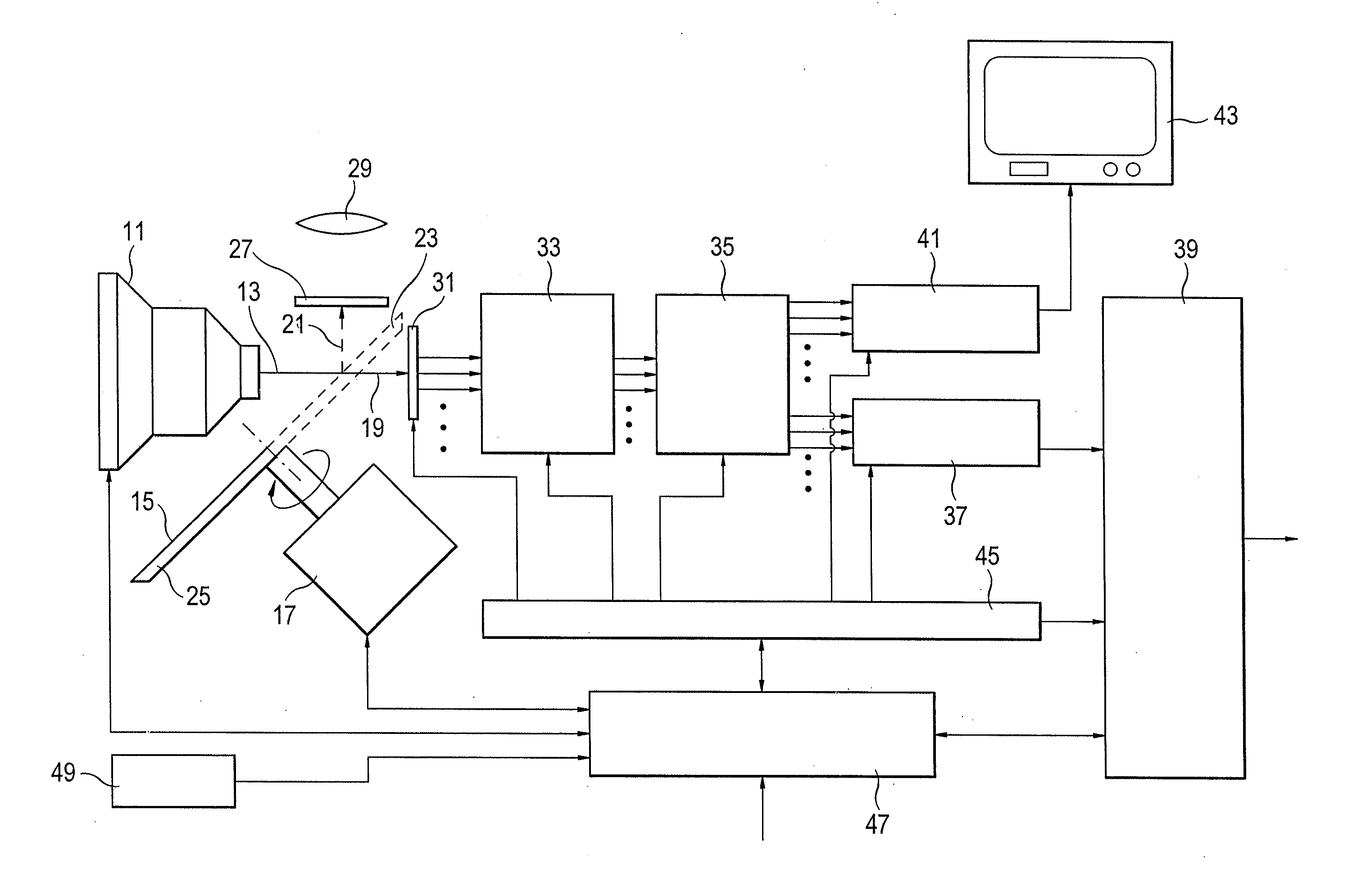
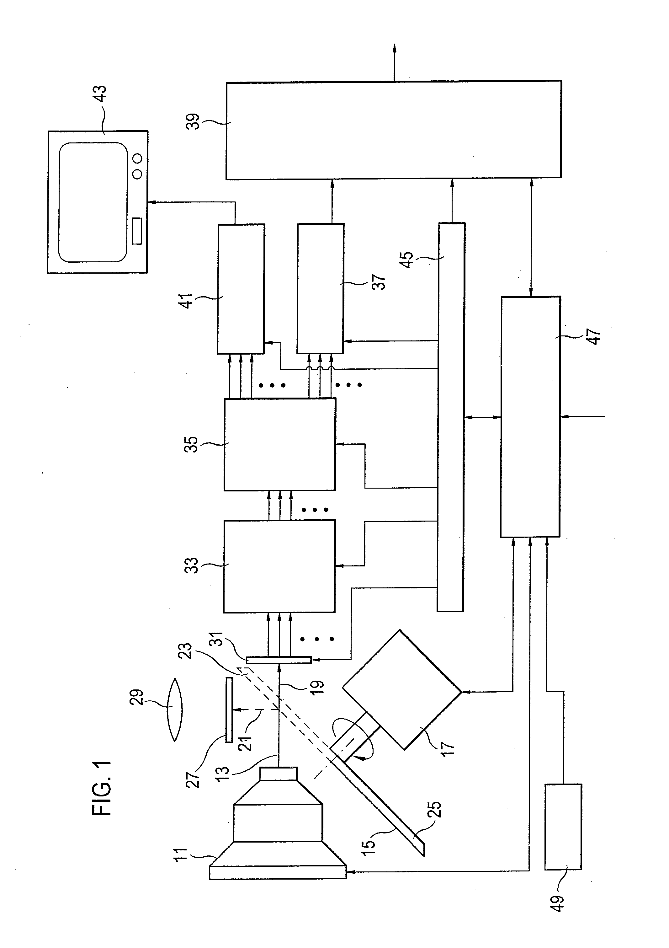
[0066]FIG. 1 shows a possible design of the motion picture camera in accordance with the invention. This has a recording optical system 11 which images the motion picture actually to be recorded along a reception beam path 13. The light incident along the reception beam path 13 is alternately transmitted in the direction of a recording beam path 19 or deflected in the direction of a viewfinder beam path 21 by means of a mirror aperture 15 which can be driven by a drive unit 17 to make a rotational movement. For this purpose, the mirror aperture 15 has a trans-mission opening 23 and a mirror coated deflection region 25.

[0067]Provided that the deflection region 25 is located in the reception beam path 13, the picture taken by the recording optical system 11 is imaged on a ground glass screen 27 such that a real image is created on this which can be observed by the cameraman by means of a viewfinder optical system 29.

[0068]In contrast, at the points in time at which—as shown in FIG. 1—...


PUM


Abstract

The invention relates to a digital motion picture camera comprising at least one optoelectronic sensor device for the recording of motion pictures. The sensor device has, in an areal arrangement, a plurality of sensor elements for the generation of a respective received signal in dependence on a light exposure. The camera further has a control device for the controlling of the read-out of the received signals of the sensor elements as well as a digitizing device for the digitizing of the received signals. The camera moreover has an optical viewfinder for the visual observation of the motion pictures to be recorded and a beam deflection device which is interposed in front of the sensor device and by means of which the reception beam path can be split at least into one recording beam path for the sensor device and one viewfinder beam path for the optical viewfinder. The sensor device can be controlled by means of the controlling device for the recording of the motion pictures at a pre-settable variable picture recording frequency.

Description

RELATED APPLICATIONS[0001]This application corresponds to and claims foreign priority benefits under 35 U.S.C. 199 (a)-(d) and (f) and 365 (b) based upon German application No. 102 10 327.5 filed Mar. 8, 2002.BACKGROUND[0002]The invention relates to a motion picture camera for full motion recordings of high picture quality such as television movies, cinema commercials, cinema movies or even industrial or medical applications. Motion picture cameras for the exposure of a photochemical negative film are known for such recordings. This recording technology allows a high resolution, large brightness dynamics and good color rendering. However, the development and the printing of such a negative film are undesirably complex and / or expensive since specialist equipment is required. Furthermore, it is required for an electronic picture processing, which has become customary in the meantime—for example for the changing of the color or for the insertion of synthetic picture elements—to subsequ...

Claims


Application Information

Patent Timeline
Patent Type & Authority Applications(United States)
IPC IPC(8): H04N5/225H04N5/232H04N5/235
CPCH04N5/2254H04N5/232H04N5/2353H04N23/60H04N23/55H04N23/73
Inventor KANDLEINSBERGER, ROBERTKHANH, TRAN QUOCKOPPETZ, MICHAELPOPP, HERMANN
Owner ARNOLD & RICHTER CINE TECH GMBH & CO BETRIEBS KG
Why Eureka
Try Eureka