Image decoding device, image decoding method, integrated circuit, and program

a decoding device and image technology, applied in the field of image decoding devices, image decoding methods, integrated circuits, and program for decoding coded images, can solve problems such as the dependence between the current block and the neighboring block, and achieve the effect of reducing the momentary increase in the amount of data transferred, preventing the interference of data transfer of the other device, and small memory bandwidth

Active Publication Date: 2010-11-11
SOVEREIGN PEAK VENTURES LLC
View PDF10 Cites 13 Cited by
  • Summary
  • Abstract
  • Description
  • Claims
  • Application Information

AI Technical Summary

Benefits of technology

[0047]With the image decoding device according to an aspect of the present invention, it is possible to suppress the momentary increase in the amount of data transferred and allow parallel decoding of the image data with a small memory bandwidth. As a result, in the case where the image decoding device shares the memory with another device and there is a large amount of data transferred for the other device, for example, the amount of data to be transferred for the image decoding device is decreased, so that the data transfer of the other device is not hindered and the processing of the other device is not adversely affected. Furthermore, the amount of data to be transferred for the image decoding device is increased when the amount of data transferred for the other device is small, so that the image decoding device can perform the image decoding process faster.

Problems solved by technology

In other words, decoding the current macroblock requires decoding of such neighboring macroblocks in advance, and for this reason such dependency between the current block and the neighboring blocks has been a problem in parallel processing.

Method used


Image

  • Image decoding device, image decoding method, integrated circuit, and program
  • Image decoding device, image decoding method, integrated circuit, and program
  • Image decoding device, image decoding method, integrated circuit, and program

Examples


embodiment 1

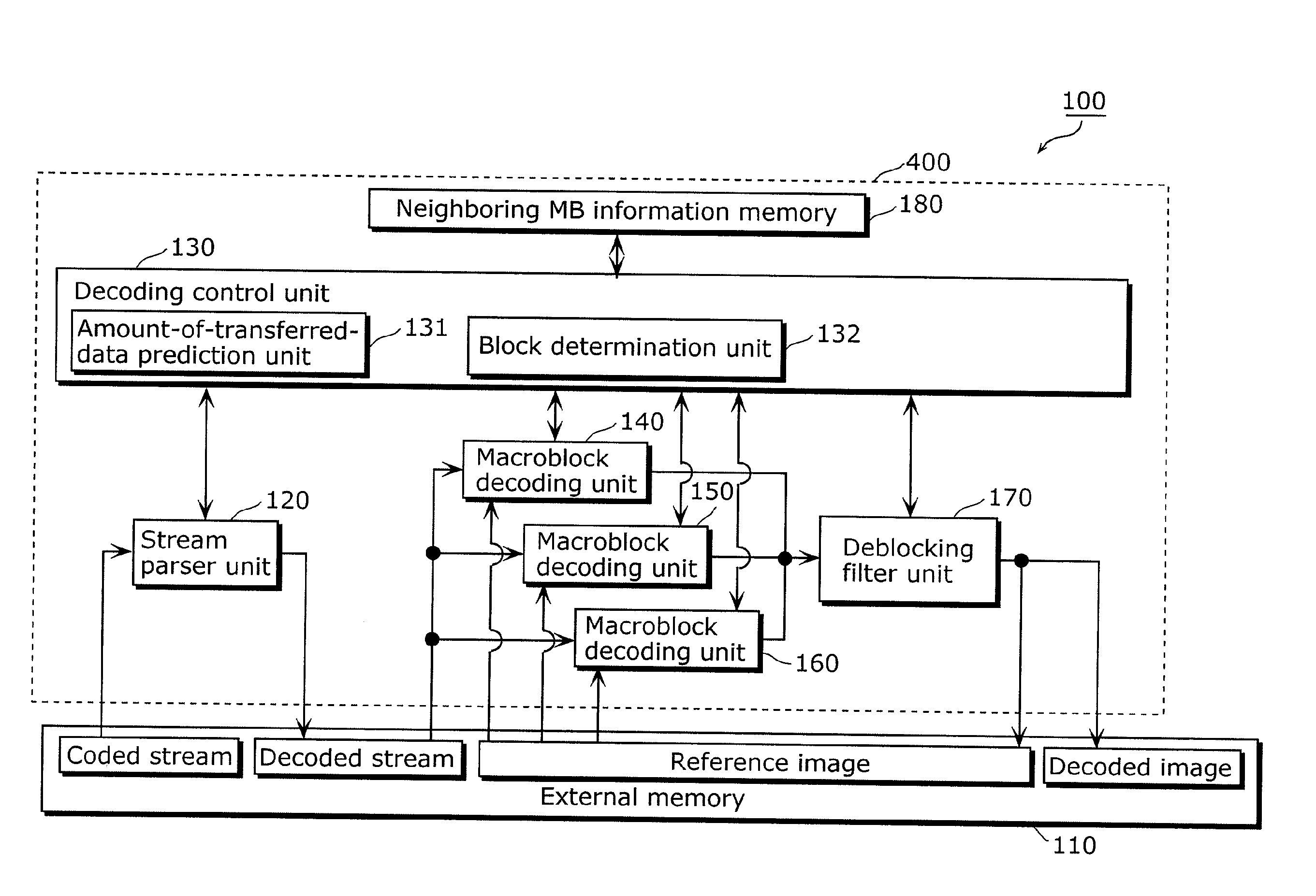
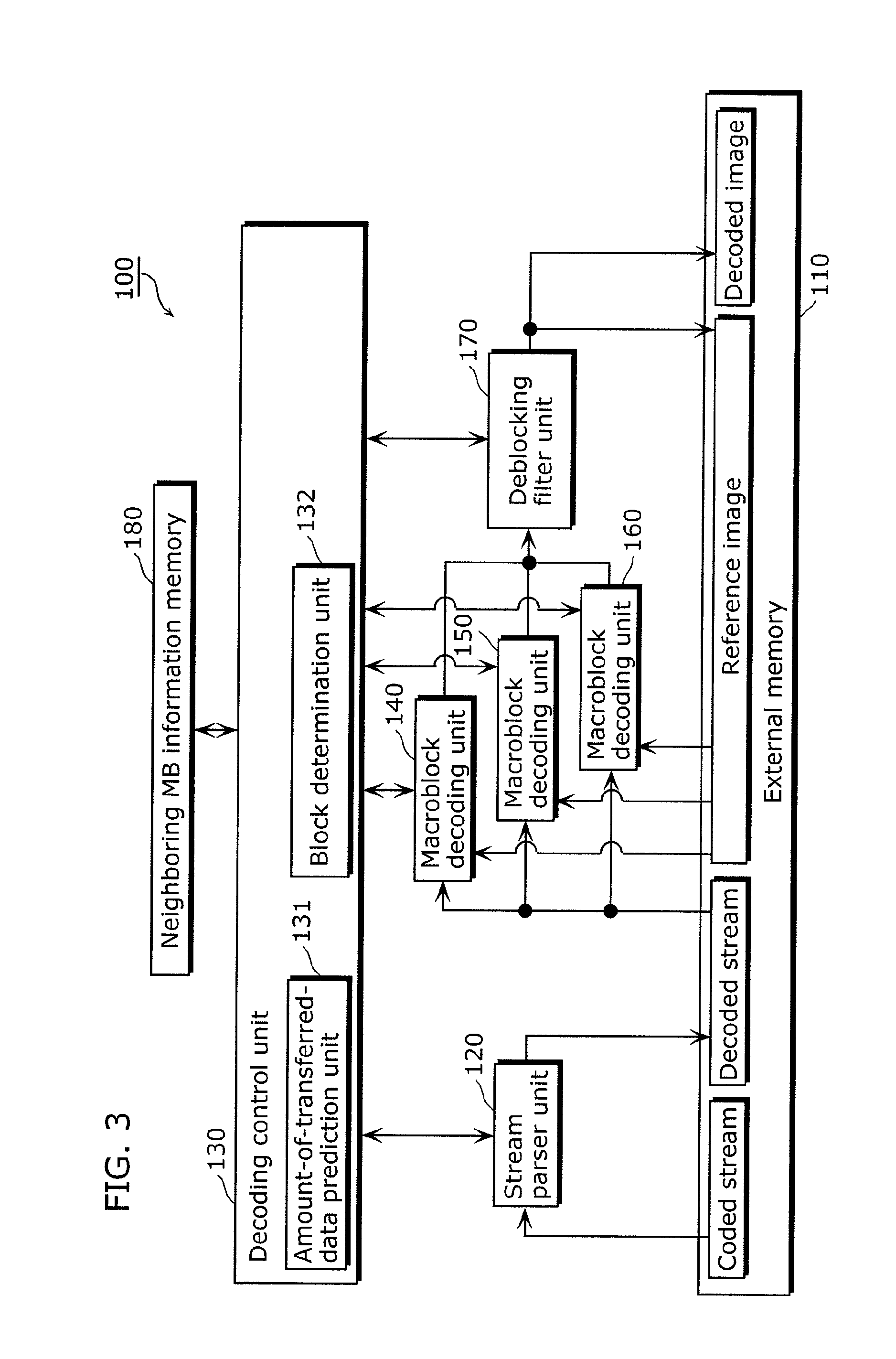
[0078]FIG. 3 is a block diagram showing a functional structure of an image decoding device 100 according to Embodiment 1 of the present invention.

[0079]The image decoding device 100 is a device that decodes, on a block-by-block basis, coded image data which is resulted from coding, on a block-by-block basis, of image data partitioned into blocks each of which has a predetermined number of pixels. Here, the blocks each having a predetermined number of pixels are macroblocks.

[0080]As shown in FIG. 3, the image decoding device 100 includes an external memory 110, a stream parser unit 120, a decoding control unit 130, a macroblock decoding unit 140, a macroblock decoding unit 150, a macroblock decoding unit 160, a deblocking filter unit 170, and a neighboring MB information memory 180.

[0081]In the neighboring MB information memory 180, information about neighboring macroblock(s) necessary for decoding a macroblock is stored.

[0082]In the external memory 110, at least one coded stream, at...

embodiment 2

[0184]In Embodiment 2, the stream parser unit 120 further sends the decoding control unit 130 block partition type information which is included in the coded image data and indicates the size of partition blocks, in the case where decoding of the coded image data involves reference to reference image(s) on a partition block-by-partition block basis, where partition blocks are resulted from partitioning of each macroblock of the coded image data into smaller blocks.

[0185]Then, the amount-of-transferred-data prediction unit 131 calculates the predictive data amount for each partition block whose size is indicated in the block partition type information, further by weighting a data amount of a reference image located at an integer-pixel position and a data amount of a reference image located at a sub-pixel position, using a probability of reference to the reference image located at the integer-pixel position and a probability of reference to the reference image located at the sub-pixel...

embodiment 3

[0249]In Embodiment 3, the stream parser unit 120 further sends the decoding control unit 130, on a macroblock-by-macroblock basis, motion information indicating an amount of motion between an image of a current macroblock to be decoded and a reference image, and the amount-of-transferred-data prediction unit 131 calculates the predictive data amount on a macroblock-by-macroblock basis by further using such motion information.

[0250]In other words, in Embodiment 3, the stream parser unit 120 sends the decoding control unit 130 at least mb_type, sub_mb_type, and mvd among the decoded parameters.

[0251]More specifically, the amount-of-transferred-data prediction unit 131 determines whether or not the reference image indicated in the motion information is located at a sub-pixel position. In the case of determining that the reference image is located at a sub-pixel position, the amount-of-transferred-data prediction unit 131 calculates a data amount of the reference image located at the s...


PUM


Abstract

An image decoding device capable of performing parallel decoding of coded image data with a small memory bandwidth while suppressing momentary increase in the amount of data transferred for the decoding. An image decoding device (100) includes: an external memory (110) which stores data of reference images; a stream parser unit (120) which decodes reference information indicating the number of reference images to be referred to on a block-by-block basis; an amount-of-transferred-data prediction unit (131) which calculates, on a block-by-block basis using the reference information, a predictive data amount of a reference image to be read out from the external memory (110); a block determination unit (132) which determines, using the predictive data amount, multiple blocks to be decoded in parallel, so as to reduce variation in amounts of data read out from the external memory (110); and macroblock decoding units (140 to 160) which decode the determined blocks in parallel.

Description

TECHNICAL FIELD[0001]The present invention relates to an image decoding device, an image decoding method, an integrated circuit, and a program for decoding coded image data.BACKGROUND ART[0002]As techniques of compress-coding (hereinafter simply referred to as “coding”) video data, MPEG (Motion Pictures Experts Group) coding methods using inter-frame differences are often employed.[0003]The MPEG coding methods make use of the video property that there is a similarity between a current frame and a frame temporally close to the current frame. Taking advantage of this property, the data amount can be reduced by predicting the current frame from the temporally-close frame and coding the difference between the input image and the predicted image.[0004]In general, a movement of an object in a frame and / or panning of a camera create a motion between frames, and thus the predicted image is generated using, as a reference image, an image shifted by the amount of motion.[0005]A high compressi...

Claims


Application Information

Patent Timeline
Patent Type & Authority Applications(United States)
IPC IPC(8): H04N7/32G06K9/36
CPCH04N19/44H04N19/573H04N19/436H04N19/423
Inventor HAYASHI, YOSHITERU
Owner SOVEREIGN PEAK VENTURES LLC
Why Eureka
Try Eureka