Portable air compressor

a portable, air compressor technology, applied in the direction of mechanical equipment, pumps, liquid fuel engines, etc., can solve the problems of reducing the efficiency and performance of pneumatic tools, and users of air compressors often cannot quickly and conveniently adjust the output of air

Inactive Publication Date: 2010-11-18
TECHTRONIC POWER TOOLS TECHNOLOGY LTD
View PDF14 Cites 50 Cited by
  • Summary
  • Abstract
  • Description
  • Claims
  • Application Information

AI Technical Summary

Problems solved by technology

Often, because of various constraints including size, weight, and available sources of electrical power to operate the air compressor, air compressors are typically remotely located from the accompanying pneumatic tools using the compressed air generated by the compressors.
As a result, a hose having a substantial length is often required to connect the air compressor to the pneumatic tool.
Using long stretches or lengths of hose typically yields an undesirably high pressure differential between the outlet of the air compressor and the pneumatic tool which, in turn, typically reduces the efficiency and performance of the pneumatic tool.
Another consequence of using pneumatic tools at a remote distance from a stationary air compressor is that a user of the air compressor often cannot quickly and conveniently adjust the output of the air compressor when switching between pneumatic tools requiring different regulated inlet pressures.
Walking to the air compressor, and then back to the worksite reduces the efficiency of the user of the pneumatic tool, which ultimately may result in increased costs associated with the construction at the worksite.

Method used


Image

  • Portable air compressor
  • Portable air compressor
  • Portable air compressor

Examples


Embodiment Construction

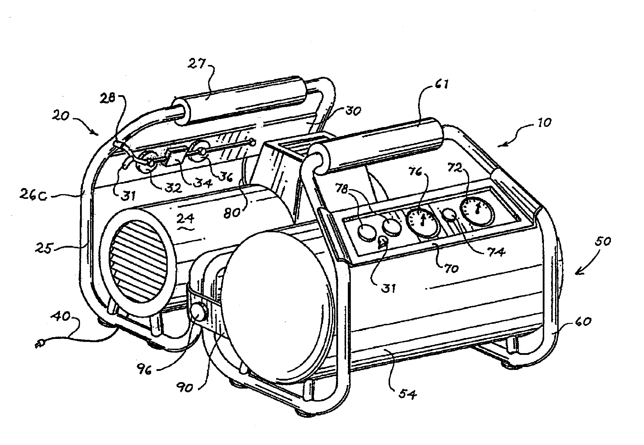
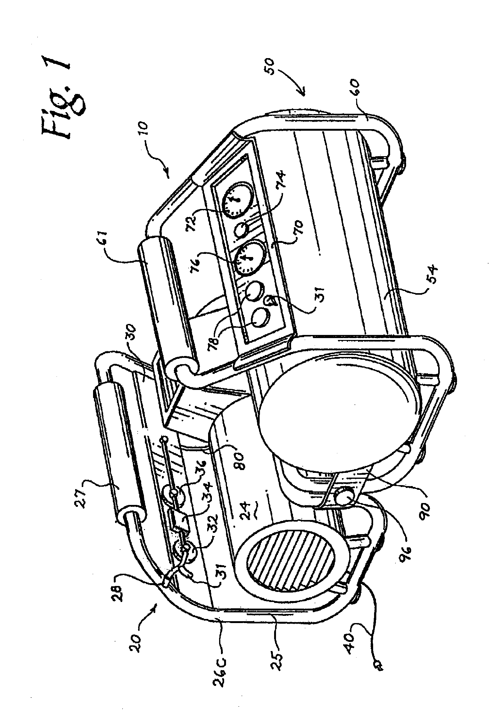
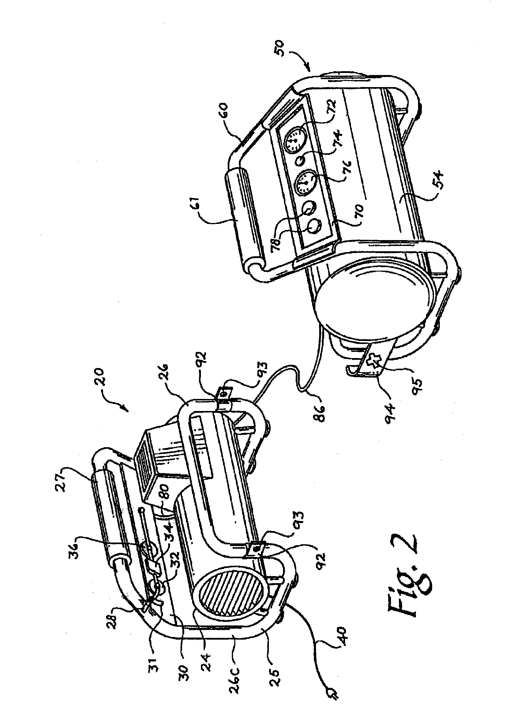
[0032]Turning now to the figures, an air compressor 10 is provided. The air compressor 10 includes an electrically driven air pump 24, a power cord 40 connectable with a source of electrical current, a first air tank 26 fluidly connected to the pump 24, a second tank 54, a removable flow path between the first tank 26 and the second tank 54, a pressure regulator 74, a tank pressure gauge 72, and an output connection 78. The air compressor 10 includes two units, the pump unit 20 and the tank unit 50. The air compressor 10 may be operated with the pump and tank units 20, 50 attached (FIGS. 1 and 5) or separated (FIGS. 2, 3, and 8). The air compressor 10 may also be operated with only the pump unit 20 to provide a source of air. Further, the tank unit 50 may be used alone to provide a source of compressed air without fluid connection with the tank unit 20.

[0033]The pump unit 20 may operate as a stand alone air compressor. The pump unit 20 is powered from a source of electrical power, s...


PUM


Abstract

An air compressor includes a compressor unit having a motor with a motor housing, a pump operably coupled to the motor and having a pump housing formed as a single piece with a portion of the motor housing, and a first tank fluidly connected to the pump to receive pressurized air from the pump when operated by the motor. The air compressor also includes a tank unit removably coupled to the compressor unit in a stacked arrangement. The tank unit includes a second tank fluidly connected to the pump to receive pressurized air from the pump when operated by the motor.

Description

CROSS-REFERENCE TO RELATED APPLICATIONS[0001]This application claims priority to co-pending U.S. Provisional Patent Application No. 61 / 176,798 filed on May 8, 2009, the entire content of which is incorporated herein by reference.[0002]This application is also a continuation-in-part of co-pending U.S. patent application No. Ser. 12 / 060,952 filed on Apr. 2, 2008, which claims priority to expired U.S. Provisional Patent Application No. 60 / 909,836 filed Apr. 3, 2007, the entire contents of both of which are incorporated herein by reference.FIELD OF THE INVENTION[0003]The present invention relates to air compressors, and more particularly to portable air compressors.BACKGROUND OF THE INVENTION[0004]Air compressors are typically used to provide compressed air for operating pneumatic tools such as nailing tools, socket-driving tools, materials-shaping tools, sanding tools, and the like. Often, because of various constraints including size, weight, and available sources of electrical power ...

Claims


Application Information

Patent Timeline
Patent Type & Authority Applications(United States)
IPC IPC(8): F04B17/00
CPCF04B41/02F04B35/06
Inventor OHI, TAKUJERABEK, JESSEBRAZELL, KENNETH M.SADKOWSKI, WILLIAM E.STRACK, RICHARD L.RITTERLING, DOUGLAS
Owner TECHTRONIC POWER TOOLS TECHNOLOGY LTD
Why Eureka
Try Eureka