Cooling arrangement for a portable air compressor

a portable air compressor and cooling arrangement technology, which is applied in the direction of positive displacement liquid engine, pump components, piston pump, etc., can solve the problems of single fan, common cooling configurations that do not supply dedicated cooling air to the head area of the compressor, and air ducting configuration(s) that are not optimized to control the distribution of all the air flow, so as to increase the cooling flow and facilitate the transition. , the effect of efficient air flow

Inactive Publication Date: 2006-08-03
BLACK & DECKER INC
View PDF24 Cites 5 Cited by
  • Summary
  • Abstract
  • Description
  • Claims
  • Application Information

AI Technical Summary

Benefits of technology

[0008] A cooling arrangement for a portable air compressor of the present invention offers several advantages. By aligning the longitudinal centerlines of both a compressor and a power unit parallel with each other and substantially perpendicular to a longitudinal axis of the air compressor, a compact arrangement of the components results. By providing two fans, a first driven by the compressor shaft and a second driven by the power unit shaft, increased cooling flow can be provided to the compressor. A ducted cover of the two fans allows for air intake through the cover and provides ducting to direct a substantially constant air flow from the power unit driven fan toward a head area of the compressor. An opposed pair of curved walls and an adapted air scoop within the ducting path smoothly transition the air approximately 90 degrees to discharge toward the compressor head area. Duct portions are provided in each of two halves of the ducted cover to provide defined duct segments which efficiently distribute the air flow and smoothly transition toward a discharge end.

Problems solved by technology

Several drawbacks exist for common portable air compressor cooling assemblies.
One drawback is that common cooling configurations may not supply dedicated cooling air to the head area of the compressor.
Another drawback is that common cooling configurations have duct portions that extend over the head area of the compressor.
Another drawback with some current compressor cooling designs is that only a single fan is used and the air ducting configuration(s) is are not optimized to control the distribution of all the air flow.

Method used


Image

  • Cooling arrangement for a portable air compressor
  • Cooling arrangement for a portable air compressor
  • Cooling arrangement for a portable air compressor

Examples


Embodiment Construction

[0021] The following description of the preferred embodiments is merely exemplary in nature and is in no way intended to limit the invention, its application, or uses.

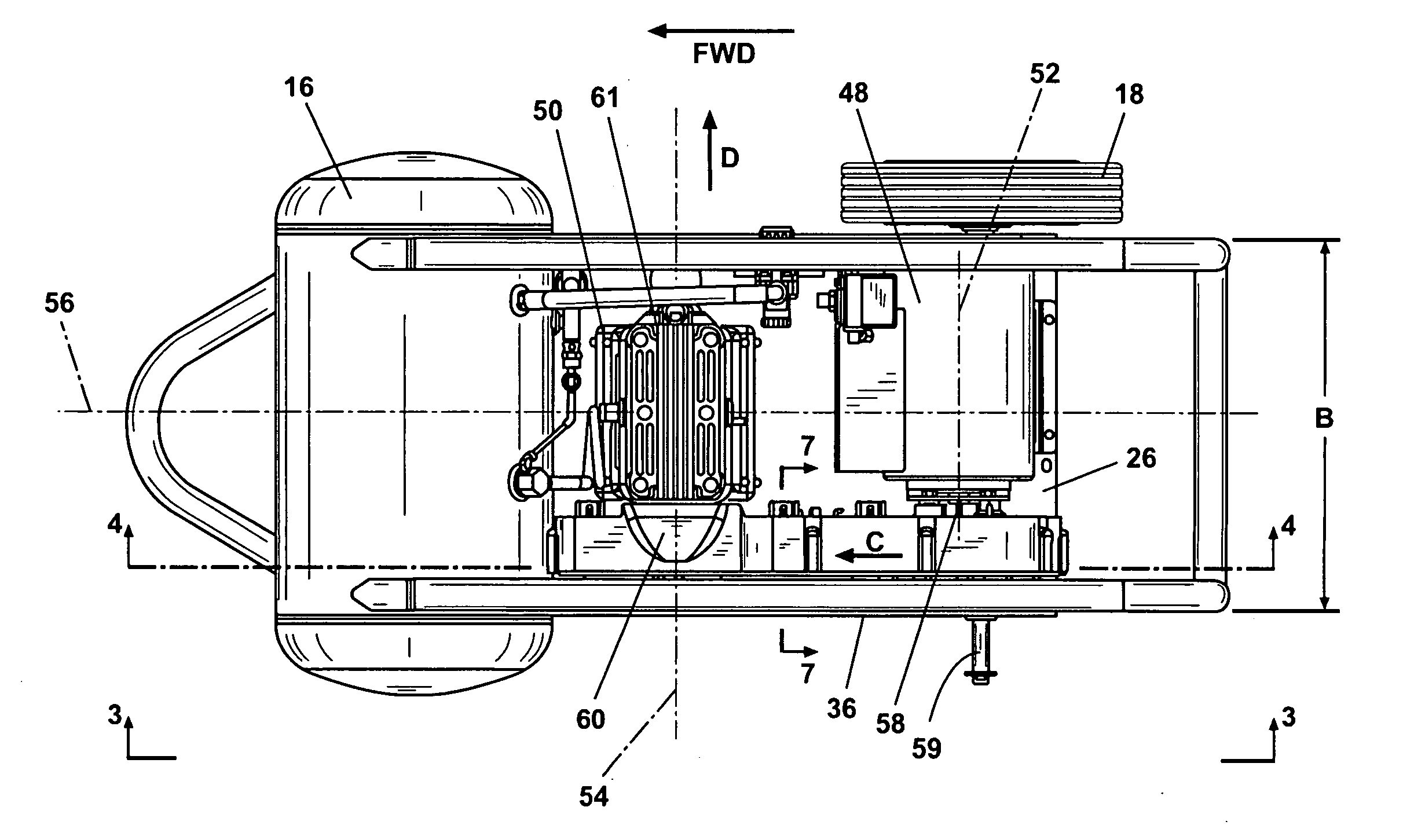
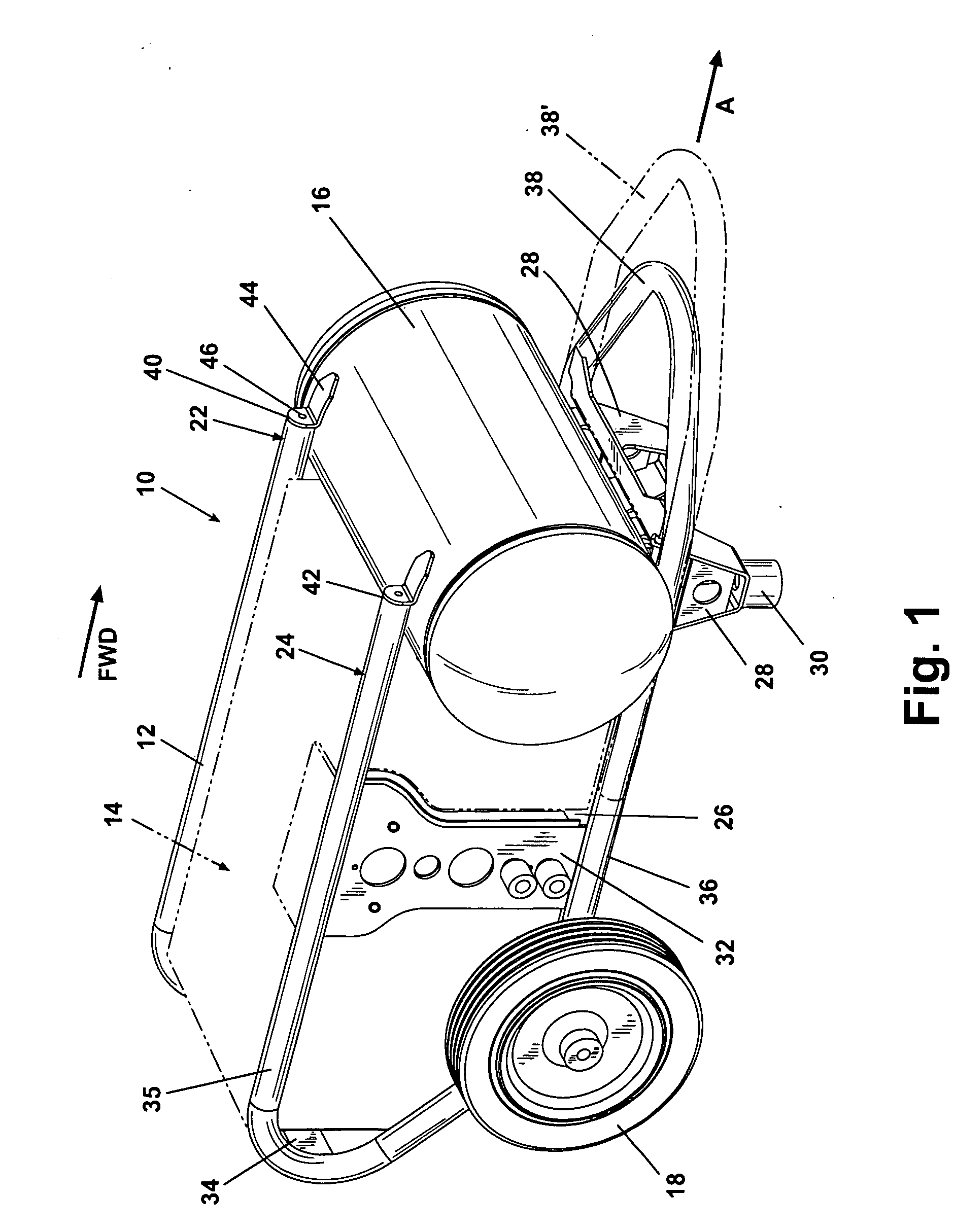
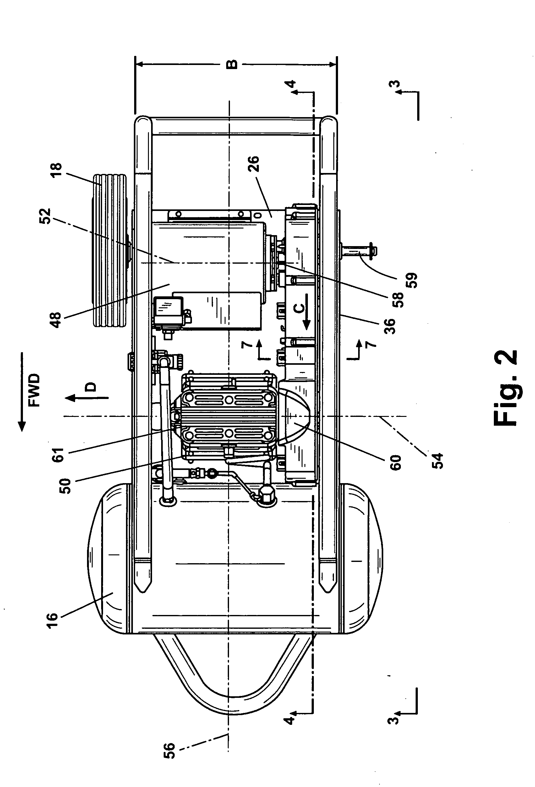
[0022]FIG. 1 identifies an air compressor assembly 10 according to one preferred embodiment of the present invention. The air compressor assembly 10 includes a frame 12, a component group 14, and a pressurized fluid containment tank 16. A first wheel 18 and a second wheel 20 are rotatably supported from the frame 12 at an aft end of the air compressor assembly 10. The frame 12 includes a first side 22 and a second side 24. The first side 22 and the second side 24 are generally tubular shaped frame members substantially formed in a parallelogram configuration having rounded corners. A support plate 26 is provided at a lower portion of the frame 12 and is mechanically joined to the first side 22 and the second side 24, respectively. A pair of support feet 28 are mechanically joined to a forward end of the frame 12 at an...


PUM


Abstract

A portable air compressor assembly includes a tubular frame having side sections and an assembly longitudinal axis. A support plate between the side sections supports a power unit having a longitudinal axis arranged perpendicular to the assembly longitudinal axis. A compressor having a compressor head and longitudinal axis is mounted to the support plate with the compressor longitudinal axis parallel to the power unit longitudinal axis and perpendicular to the assembly longitudinal axis. A fan connected to the power unit generates an air flow. A ducted cover enclosing the fan includes an air passage directing the air flow from the fan to the compressor head. The ducted cover includes inner and outer covers each including a portion of the air passage. An air scoop extends into the outer cover portion of the air passage to redirect the air flow.

Description

FIELD OF THE INVENTION [0001] The present invention relates in general to air compressors and more specifically to an apparatus and method for cooling a compressor of a portable air compressor. BACKGROUND OF THE INVENTION [0002] Air compressors normally provide a source of pressurized air which is temporarily stored under pressure in a tank. A motor, typically an electric motor or a combustion engine, is connected to a compressor unit. The compressor unit typically includes a piston assembly having a piston slidably mounted in a cylinder, the piston compressing air from the atmosphere and forcing it into the fluid pressure tank for temporary storage. The work involved in compressing atmospheric air and the friction of the moving piston within the cylinder generate heat which must be dissipated. Cooling fins are commonly provided on the cylinder for air near the cylinder to convectively cool the piston assembly. Fans are also known which force air toward and about the piston assembly...

Claims


Application Information

Patent Timeline
Patent Type & Authority Applications(United States)
IPC IPC(8): F04B17/00
CPCF04B35/04F04B35/06F04B39/066F04B39/12F04B41/02
Inventor BARON, MICHAEL P.CHREENE, DAVID E.SPENCER, WILLIAMEKSTROM, ERIK A.
Owner BLACK & DECKER INC
Why Eureka
Try Eureka