Sputtering target and method/apparatus for cooling the target

a target and sputtering technology, applied in the direction of electrolysis components, vacuum evaporation coatings, coatings, etc., can solve the problems of non-uniform sputtering, non-uniform eroding of the target surface, degrading the cooling of the target tube in this area, etc., to promote and enhance the cooling of the target tube, promote more uniform sputtering, and enhance cooling flow

Inactive Publication Date: 2009-07-14
GUARDIAN GLASS LLC
View PDF9 Cites 1 Cited by
  • Summary
  • Abstract
  • Description
  • Claims
  • Application Information

AI Technical Summary

Benefits of technology

[0004]It has been found that non-uniform sputtering, i.e., non-uniform eroding of the target surface, is caused at least in part by non-uniform cooling of the interior surface of the outer target tube. Specifically, in a typical target water-cooling arrangement, cooling water flows through the inner magnet bar support tube and reverses direction to flow between the inner support tube and outer target tubes, it has been discovered that air bubbles and “dead water” zones are likely to form at or near the inner tube outlet jets where the cooling water reverses direction (sometimes referred to herein as the “flow-reversal zone”). It has also been discovered that insufficient circulation of cooling water along the inner magnet support bar (i.e., in the radial space or region between the magnet bar and target tube), further degrades the cooling of the target tube in this area. Resulting localized hot spots on the target tube surface can lead to non-uniform sputtering and decreased target component life.
[0005]In accordance with an exemplary embodiment of this invention, mechanical flow enhancement devices are attached to the external surface of the inner magnet bar support tube to promote and enhance cooling of the target tube. More specifically, two enhancement devices are provided that may be used alone or in combination to enhance cooling flow and thus promote more uniform sputtering.
[0006]The first device is a baffle in the form of a flat plate with an array of apertures formed therein. The baffle is secured to the exterior of the inner magnet bar support tube by any suitable fastening bracket adjacent that end of the inner support tube where the cooling water exits into the space between the inner and outer tubes. In this regard, the cooling water exits the inner tube in the form of a plurality of jets and almost immediately reverses direction to flow between the inner support tube and the outer target tube. By forcing the water to flow through the baffle, sufficient turbulence is created to avoid or at least reduce the creation of air bubbles and / or dead water zones at or near the cooling water flow-reversal zone.
[0007]The second device is a flow member in the form of spiral vane segments that are attached to the inner support tube and extend substantially the entire distance between the baffle and the opposite end of the inner and outer tubes. The series of discontinuous vane segments provide an axially extending space on the underside of the inner support tube to accommodate the axially extending magnet bar. The spiral vane segments cause the cooling water that otherwise might stagnate under the magnet bars to continuously circulate into and out of this region to thereby more uniformly cool the target or outer tube, and thus enhance sputter coating uniformity.

Problems solved by technology

It has been found that non-uniform sputtering, i.e., non-uniform eroding of the target surface, is caused at least in part by non-uniform cooling of the interior surface of the outer target tube.
It has also been discovered that insufficient circulation of cooling water along the inner magnet support bar (i.e., in the radial space or region between the magnet bar and target tube), further degrades the cooling of the target tube in this area.
Resulting localized hot spots on the target tube surface can lead to non-uniform sputtering and decreased target component life.

Method used


Image

  • Sputtering target and method/apparatus for cooling the target
  • Sputtering target and method/apparatus for cooling the target
  • Sputtering target and method/apparatus for cooling the target

Examples


Embodiment Construction

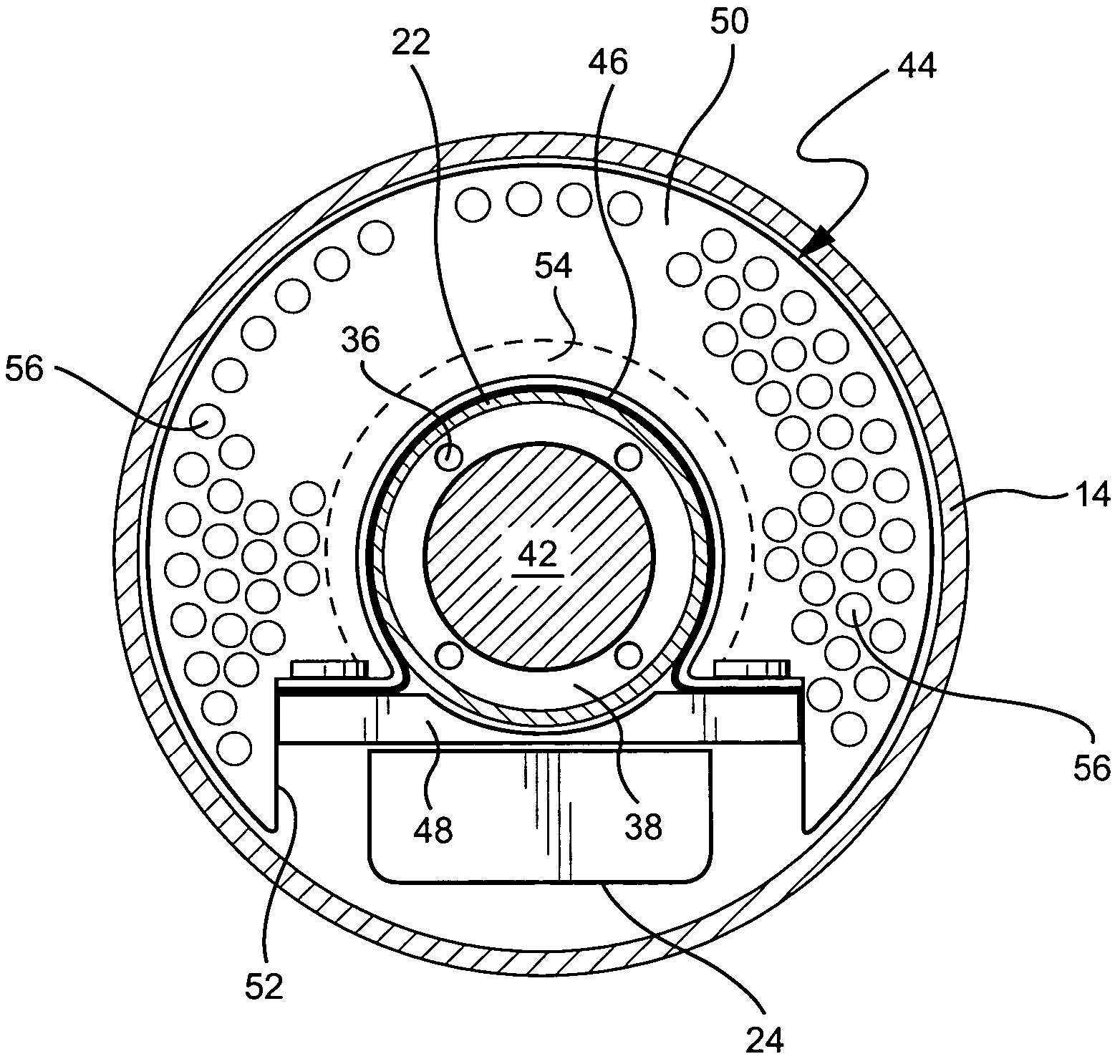
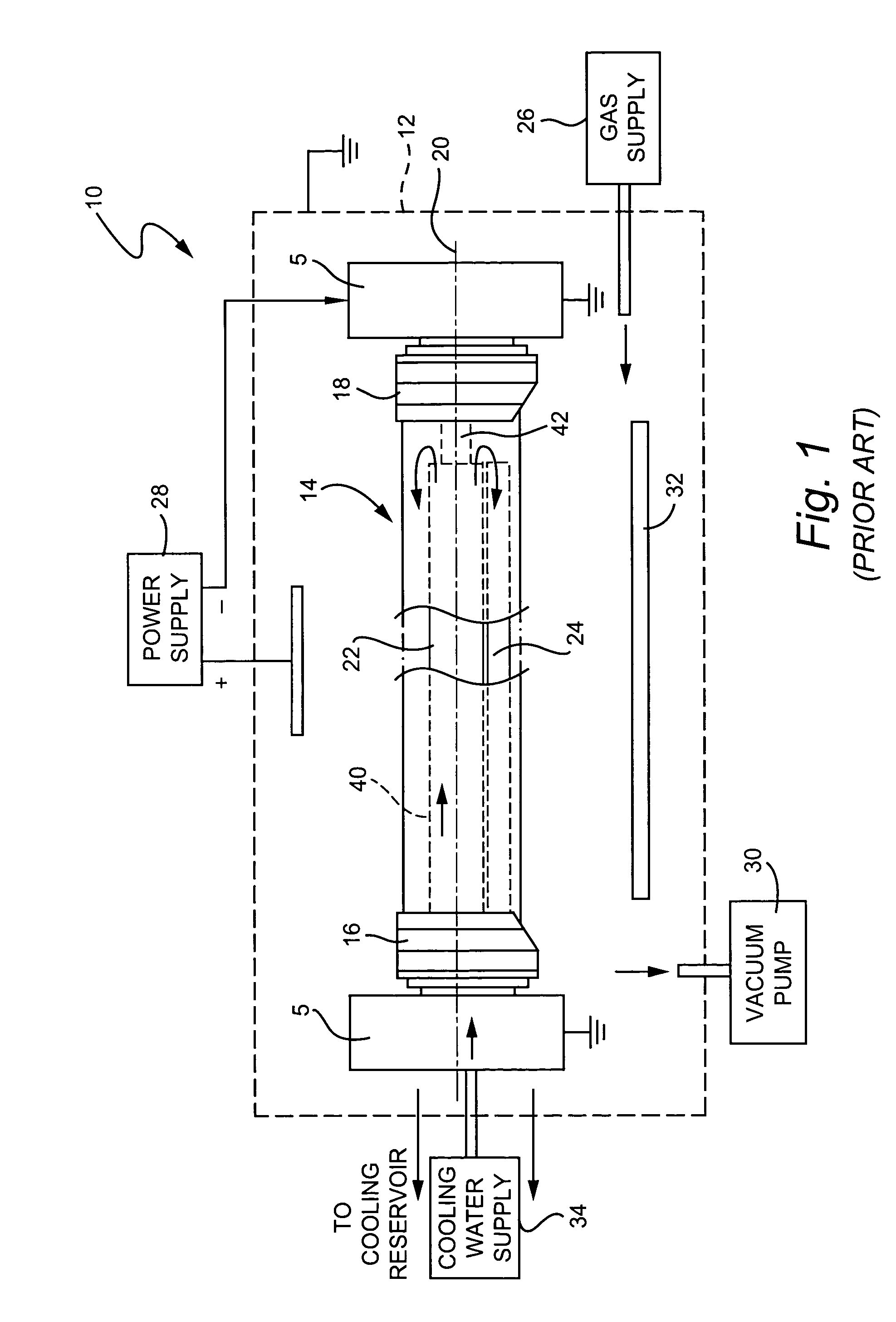
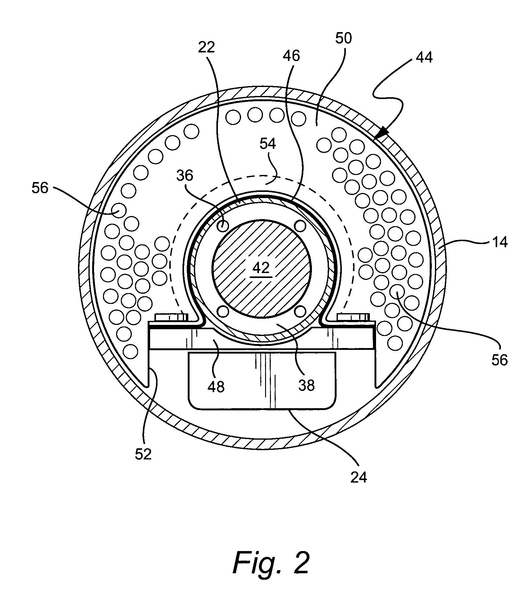
[0016]FIG. 1 illustrates in simplified form a conventional magnetron sputtering apparatus 10. The apparatus includes metal walls 12 of the vacuum chamber in which sputtering is performed; a cylindrical rotating target (or outer target tube) 14 that is supported at opposite ends by a bearing block 16 and a drive block 18 so that the target is rotatable about axis 20; and an inner magnet bar support tube 22 that supports a magnet carrier and associated magnets (represented by the single block 24) that extends along the underside of the inner support tube 22, substantially the entire length of both the inner support tube and the outer target tube. Gas is supplied to the vacuum tube via an external gas supply 26 while power is supplied via external power supply 28. The vacuum tube is evacuated by a vacuum pump 30.

[0017]In a typical sputtering process, the plasma formed when an electrical potential is applied to the cathode target bombards the target and the dislodged particles fall on t...


PUM

PropertyMeasurementUnit
lengthaaaaaaaaaa
shapeaaaaaaaaaa
angleaaaaaaaaaa

Abstract

A sputtering target includes an outer target tube, an inner support tube supporting a magnet carrier bar extending along substantially the entire length of the inner support tube; and a water cooling circuit including at least one passageway within the inner support tube with an inlet at one end thereof adapted to receive cooling water from an external source, at least one outlet aperture at an opposite end thereof opening to a cooling plenum radially between the inner support tube and the outer target tube; and a baffle comprising a substantially flat plate attached to the inner support tube adjacent the opposite end, the plate extending radially within the plenum between the inner support tube and the outer target tube and having an array of flow apertures therein.

Description

[0001]This invention relates to a sputtering target and, more specifically, to an internal magnet support tube configuration with cooling enhancement features.BACKGROUND OF THE INVENTION[0002]The use of sputtering in order to deposit coatings on substrates is known in the art. For example, and without limitation, see U.S. Pat. Nos. 5,403,458; 5,317,006; 5,527,439; 5,591,314; 5,262,032; and 5,284,564. Briefly, sputter coating is an electric-discharge-type process which is conducted in a vacuum chamber in the presence of at least one gas. Typically, a sputtering apparatus includes a vacuum chamber, a power source, an anode, and one or more cathode targets which include material used to create a coating on an adjacent substrate. The target may include an outer tube enclosing a magnet bar assembly including and an associated inner magnet bar support tube. More specifically, in certain known arrangements, the one or more magnet bars are secured to the underside of the support tube along ...

Claims


Application Information

Patent Timeline
Patent Type & Authority Patents(United States)
IPC IPC(8): C23C14/35
CPCH01J37/3497H01J37/3405
Inventor RICHERT, HENDRYKKRILTZ, UWESCHMIDT, ARMINWEIDL, ROLANDJANICKE, GERALD
Owner GUARDIAN GLASS LLC
Why Eureka
Try Eureka